Continue to Site

Eng-Tips is the largest engineering community on the Internet

Intelligent Work Forums for Engineering Professionals

  • Congratulations KootK on being selected by the Eng-Tips community for having the most helpful posts in the forums last week. Way to Go!

Direct Bearing Splice 4

Status
Not open for further replies.

Veer007

Civil/Environmental
Sep 7, 2016
379
Hey Guys, this may sound silly, I have a suspicion, Have you ever thought about this direct bearing splice connection? Is this structurally acceptable when two part connected with the bolted connection that one part allowing another part to bear itself directly on?
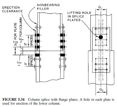
FIGURE-5.34-Column-splice-with-flange-plates.-A-hole-in-each-plate-is-used-for-erection-of-the-lower-column_ryqbck.jpg


Thanks in advance!!
 
Replies continue below

Recommended for you

Direct bearing splices are doable. I know Eurocode requires you to be able to transfer at least 25% of the compression force in the splice (not by direct bearing, but through plates and bolts). Also keep 2nd order effects in mind.

See EC1993-1-8 6.2.7.1 (14) and (15)
 
Interesting, 75% load can be transferred through direct bearing, right?

Thanks in advance!!
 
I've read it as 100% can be transferred via direct bearing, but the splice should still have capacity to transfer 25% of the design load.

You can find some information and calculation examples on page 172 and onward in SCI P358


Addionaly there was a short article in a publication that examined the 25% rule.


Also keep in mind if your column need to act as vertical ties due to robustness, then tension would probably dictate the design.

This is all Eurocode-based. Maybe other codes states something entirely different.
 
We have a project in our office nearing completion. A fairly large tower.

The steel supplier chose to not mill the ends of each piece to provide direct bearing. As a note, we delegate all connections where we practice including splice details, we provide the loads required and that's it. Rather they just designed the plates and bolts to take it all. But, they did not design them as slip critical.

Want to guess what happens every few months as they get close to needing the next column splice? The weight of the structure finally overcomes the friction in the plates and the whole building bangs and shakes while it closes the small erection gaps. The first time it happened, the entire construction site was evacuated and we were called in to review. Couldn't find anything wrong with anything on site after a thorough review. Allowed construction to proceed, couple months later another bang and shake. Finally clued in what was happening. Now we essentially know when to expect a call based on the construction schedule. Luckily they're done erecting columns and only have a few floors of steel and hollowcore left to put up.
 
That is an interesting anecdote jayrod12. Were the connections plain bearing or slip critical? I often wonder about the potential for a similar phenomenon in braced frame connections.

To OP's original question, it my understanding that it is absolutely the intent that these splices function primarily in direct bearing. The tension capacity in the splice plates and bolts is really about:

1) Some nominal tension capacity as mentioned previously.

2) Some nominal bending capacity to prevent pin-pin buckling at the splice (dependent on design assumptions).

3) Shear connection.

3) Generally snugging and plumbing things up during erection.

Which of those things applies to a given situation depends on the particulars of that situation.

 
Thanks ,

Thanks all

So, all bolted column splice which have a erection gap-1/2" between primary and secondary members must have been designed as slip critical and bolted connection which has fin-fin mill end at each member to allow direct bearing can be designed as bearing type, Am I right?

Thanks in advance!!
 
The connection was designed as a bolted bearing only connection, not slip critical. But in hindsight, it should have been either slip critical or milled ends for direct bearing.

But slip critical on a connection of that magnitude would've been cost prohibitive in our case due to the load transfer requirements.

Live and learn sometimes.
 
I've read it as 100% can be transferred via direct bearing, but the splice should still have capacity to transfer 25% of the design load.

This is the interpretation in my part of the world as well. Locally we design (or are required to design) the splice plates for 15% of the flange load, and to transfer all of the web shear via the web connection. The connection shown in the original post has no web connection so would not be a valid connection round these parts.

Flange load is derived from the combination of flexure and axial load. All the flexure is assumed to be carried by the flanges, so the flange force is the moment divided by the distance between flange centroids +/- half the axial load. Splice pates are checked for block shear, gross/net tension, compression buckling, etc.

I've seen my fair share of bad splices, where the expectation was preparation for end bearing via milling ends or cutting to be appropriately flush and square. But what turned up on site looked like someone had just cut the end not even square. It turns into an expensive fix to rectify, on 10 storey building a few years back that we got involved in we ended up having to weld all the column splices because the alignment was so poor and the contractor didn't rectify it when they had the chance by taking it down and doing the proper end prep (carried on in the hope it would be ok or something I guess, and ignoring all advice to the contrary). This not only took ages but must have cost them a bucket load of $$, it isn't cheap prepping and site welding 350x50mm thick flanges on ~50 columns with 3 splices per column over the height of the building. All because someone couldn't cut or mill the ends of the member correctly during fabrication.

On my own designs I now make it a habit to clearly identify on the drawings where end bearing prep is going to be required, rather than assuming it will be done because the two ends might be drawn in contact. This being at bearing column splices, and at baseplates where the welds are not sufficient for the compression load case.

 
Anyone, please advise, my assumption was right or wrong?

Thanks in advance!!
 
all bolted column splice which have a erection gap-1/2" between primary and secondary members must have been designed as slip critical
May not have been designed as slip critical. Should it have been, probably, but I wouldn't be making the assumption that it must have been designed this way without checking it.

bolted connection which has fin-fin mill end at each member to allow direct bearing can be designed as bearing type
for compression yes, provided your end preparation meets the requirement in your code.

 
Agent666 said:
May not have been designed as slip critical. Should it have been, probably, but I wouldn't be making the assumption that it must have been designed this way without checking it.
Thanks, So it's not mandatory to design as slip critical, we have to check before going with either slip critical or bearing type?

Thanks in advance!!
 
Read your code, I'd expect the answer in there somewhere regarding whether you specifically need slip critical bolting for a splice or if it's up to the designers judgement. Tensioned bearing type bolts may be noted in your local code (whatever that is) as being sufficient in typical 2mm oversized holes (and you wouldn't be using slotted holes in a column right)

 
Status
Not open for further replies.

Part and Inventory Search

Sponsor