Tygra_1983
Student
- Oct 8, 2021
- 125
Hi all,
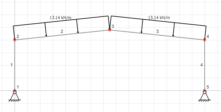
I am trying to solve for a gable frame using the Direct Stiffness Method. The frame is obviously constructed of two rafters and two columns. I am quite confused: I am getting the correct results for the columns, but not for the rafters. I am comparing my results to those in ETABS for confirmation of the correct results. I am using my beloved Octave, so I need someone who uses either Octave or MATLAB.
The frame consists of two 8 metre columns, and two 15.083 metre rafters at an angle of 6 degrees to the horizontal. The UDL on the rafters is 13.14 kN/m

Here is the code from Octave:
The force vector gives the axial force, shear and bending moment for a single member over two joints. There are three degress of freedom at each joint.
This is the results for the column:
These results are correct!!
These are the results for the rafter:
These results are incorrect!
I have examined everything and cannot see what is the issue. I know this question is quite time comsuming, so I deeply thank anyone that attempts to help!
I am trying to solve for a gable frame using the Direct Stiffness Method. The frame is obviously constructed of two rafters and two columns. I am quite confused: I am getting the correct results for the columns, but not for the rafters. I am comparing my results to those in ETABS for confirmation of the correct results. I am using my beloved Octave, so I need someone who uses either Octave or MATLAB.
The frame consists of two 8 metre columns, and two 15.083 metre rafters at an angle of 6 degrees to the horizontal. The UDL on the rafters is 13.14 kN/m

Here is the code from Octave:
Code:
clear, clc, close all

[b]% Structural data[/b]

     E = 2.1E+08;
     Ic = 8.74999E-04;  [b]Second Moment areas of Columns[/b]
     Ac = 0.01442;      [b] Cross-sectional areas of columns[/b]
     Lc = 8;
     n = 15;
     alpha = 6          [b]Slope of roof in degrees[/b]
     matrix = zeros(6,n);
     Lr = 15/(cosd(alpha))
     Ir = 2.94331E-04   [b]Second Moment areas of rafters[/b]
     Ar = 0.00856;       [b] Cross-sectional areas of rafters[/b]

     [b]% Local stiffness matrix for columns[/b]

     Kc = [1 0 0 -1 0 0
           0 12 6*Lc 0 -12 6*Lc
           0 6*Lc 4*Lc^2 0 -6*Lc 2*Lc^2
          -1 0 0 1 0 0
           0 -12 -6*Lc 0 12 -6*Lc
           0 6*Lc 2*Lc^2 0 -6*Lc 4*Lc^2]

      [b]% Local stiffness matrix for rafters[/b]

      Kr = [1 0 0 -1 0 0
            0 12 6*Lr 0 -12 6*Lr
            0 6*Lr 4*Lr^2 0 -6*Lr 2*Lr^2
           -1 0 0 1 0 0
            0 -12 -6*Lr 0 12 -6*Lr
            0 6*Lr 2*Lr^2 0 -6*Lr 4*Lr^2]

       [b]% For loop to complete the local stiffness matrices[/b]

       for i = 1:6
            if i == 1 || i == 4
            Kc(i,:) = Kc(i,:)*(E*Ac)/Lc;
            Kr(i,:) = Kr(i,:)*(E*Ar)/Lr;
           else
           Kc(i,:) = Kc(i,:)*(E*Ic)/Lc^3;
           Kr(i,:) = Kr(i,:)*(E*Ir)/Lr^3;
             end
         end

      [b] % Transformation matrices[/b]

       T1 = matrix; [b]For Left Column[/b]
       T1(2,1) = -1;
       T1(1,2) = 1;
       T1(3,3) = 1;
       T1(5,4) = -1;
       T1(4,5) = 1;
       T1(6,6) = 1

       T4 = matrix; [b]For right column[/b]
       T4(2,13) = -1;
       T4(1,14) = 1;
       T4(3,15) = 1;
       T4(5,10) = -1;
       T4(4,11) = 1;
       T4(6,12) = 1;


       T2 = matrix;
       T2(1,4) = cosd(alpha);   [b]For left rafter[/b]
       T2(1,5) = sind(alpha);
       T2(2,4) = -sind(alpha);
       T2(2,5) = cosd(alpha);
       T2(3,6) = 1;
       T2(4,7) = cosd(alpha);
       T2(4,8) = sind(alpha);
       T2(5,7) = -sind(alpha);
       T2(5,8) = cosd(alpha);
       T2(6,9) = 1;

       T3 = matrix;
       T3(1,7) = cosd(-alpha);  [b]For right Rafter[/b]
       T3(1,8) = sind(-alpha);
       T3(2,7) = -sind(-alpha);
       T3(2,8) = cosd(-alpha);
       T3(3,9) = 1;
       T3(4,10) = cosd(-alpha);
       T3(4,11) = sind(-alpha);
       T3(5,10) = -sind(-alpha);
       T3(5,11) = cosd(-alpha);
       T3(6,12) = 1;

       [b]% Assembly[/b]

       km1 = T1'*Kc*T1;
       km2 = T2'*Kr*T2;
       km3 = T3'*Kr*T3;
       km4 = T4'*Kc*T4;

       Ks = km1 + km2 + km3 + km4

     [b] % Application of boundary conditions[/b]

      Ks(:,[1,2,13,14]) =[];
      Ks([1,2,13,14],:) =[];

      [b]% Applying loading[/b]

      w = 13.14;
      V = w*Lr/2;
      M = w*Lr^2/12;

      F = zeros(n,1);
      F(4) = -V*sind(alpha);
      F(5) = V*cosd(alpha);
      F(6) = M;
      F(8) = 2*V*cosd(alpha);
      F(9) = 0;
      F(10) = V*sind(alpha);
      F(11) = V*cosd(alpha)
      F(12) = -M;
      F([1,2,13,14]) = []

      [b]% Solving[/b]

      U = inv(Ks)*F

      Ux = [0 0 U(1:10)' 0 0 U(11)'];
      fx = T2*Ux'
      force = Kr*fx
The force vector gives the axial force, shear and bending moment for a single member over two joints. There are three degress of freedom at each joint.
This is the results for the column:
Code:
Ux = [0 0 U(1:10)' 0 0 U(11)'];
      fx = T1*Ux'
      force = Kc*fx

      force =

  -197.1000
   108.3198
          0
   197.1000
  -108.3198
   866.5586
These results are correct!!
These are the results for the rafter:
Code:
Ux = [0 0 U(1:10)' 0 0 U(11)'];
      fx = T2*Ux'
      force = Kr*fx

      force =

  -128.329
   -85.605
  -617.462
   128.329
    85.605
  -673.685
These results are incorrect!
I have examined everything and cannot see what is the issue. I know this question is quite time comsuming, so I deeply thank anyone that attempts to help!
