Continue to Site

Eng-Tips is the largest engineering community on the Internet

Intelligent Work Forums for Engineering Professionals

  • Congratulations cowski on being selected by the Eng-Tips community for having the most helpful posts in the forums last week. Way to Go!

Discepancy in AISC Seismic Design Manual 2nd edition vs. 2012 IBC SEAOC Seismic Design Manual

Status
Not open for further replies.

E720

Structural
Feb 20, 2018
71
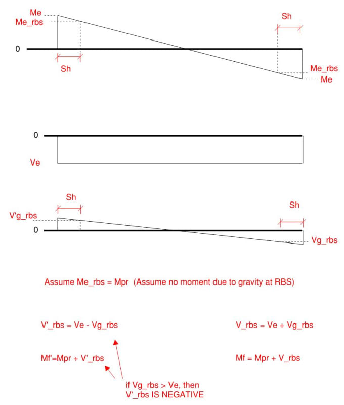
We are writing a spreadsheet for an RBS connection calc. Both seismic design manuals go through this. Part of the process is computing the maximum moment at the face of the column. On page 4-64 of the AISC Manual it has the equations for M_f and M'_f. Looking at the equation for M_f looks correct by summing the moments as shown in the free body diagram. The equation for M'_f (the moment at the face of the column on the other end of the beam)looks incorrect if you draw out the free body diagram, should be M'_f = M_PR - V'_RBS * S_h. This is what the SEAOC Manual has (pg 28). Is the SEAOC Manual correct like it looks like or am I missing something? I have checked the errata on the AISC Manual and it doesn't say anything about it.

Thanks,
 
Replies continue below

Recommended for you

I didnt say this before but I am looking at Volume 4 of the 2012 SEAOC Manual.
 
When the maximum moment M_f occurs on side I of the beam, the J side of the beam should have a shear at the RBS that is lower than on side I.... just because the gravity portion of that loading will not be increasing the moment. But, assuming that portion of V_RBS due to the hinging shear is greater than gravity shear, the AISC equation seems more correct to me than the SEAOC equation.

Regardless, this is something of a moot point, isn't it? The controlling moment at the face of each column will always be when the moment from seismic and the moment from gravity are additive.
 
I believe the only thing it affects is the panel zone check, when checking whether you need doubler plate(s) or not. "AISC Seismic Provisions Section E3.6e specifies that the required panel zone shear strength be calculated by summing the moments at the column faces as determined by projecting the expected moments at the plastic hinge points to the column faces, in this example, M_f and M'_f". Looking at a FBD of both sides it still looks to me like on one side it will be additive and on the other side they will be opposite in sign. But I have known to be wrong (just once though).
 
Yes, if you have moment connections on both sides, then it would affect the panel zone shear. I might give the equation as something more like:

far side
M'_f = M_PR + (V'_RBS - V_gravity) * S_h

near side
M_f = M_PR + (V_RBS + V_gravity) * S_h

I'm probably not using the exact definitions that they do. But, I hope you get my point. I'm using V'_RBS = V_RBS = 2*Mpr / (L_hinge). That will always increase the moment at the face of the column, whereas the Vgravity will increase it on one side and decrease it on the other.
 
I don't have the SEAOC manual, but the only way you'd subtract it would be if V'g_rbs was greater than Ve.

Capture_yvafh2.jpg
 
Now it makes sense. Thank you so much.
 
Just realized I have a mistake in my Mf equations, obviously V_rbs should be multiplied by Sh
 
Status
Not open for further replies.

Part and Inventory Search

Sponsor