Eng-Tips is the largest engineering community on the Internet

Intelligent Work Forums for Engineering Professionals

Distance between two passing axes 1

Status
Not open for further replies.

maripali

Mechanical
Mar 15, 2014
63
0
0
LT
Hi all,

When I measuring distance between passing axes in a 3D space, Inventor gives the shortest distance as I need.
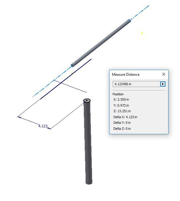
But when cylindrical faces or axes are too short Inventor measures the shortest distance from the end of axis.
Is there any way to measure the shortest distance as between endless axes?
 
Replies continue below

Recommended for you

Hi
1) You could insert a work axis on the cylinder's center axis and measure to the work axis.

2) When selecting items to be measured, you often have the option to -right-click- "Select Other...".
Then choose from other features/faces that are within the field of the cursor.
The center axis of the part may be included in this list.


STF
 
Thanks SparWeb,

When I am catching axes of the cylindrical faces Inventor measures distance from the ends of cylinders. This distance is not acceptable.
Inventor does not calculate virtually extended axes. Axes or cylindrical faces have to be as long as need to draw perpendicular between them.
When I draw Axis on the cylindrical face it is got longer than cylindrical face but its too short for the measuring as well.
If I could to resize that axis I am sure for the getting right result.

Regards
 
Either I am misunderstanding your problem, or you should try it again.
I can replicate both of my suggested solutions and get the results I think you are asking for.
There are many options available to you when using the Measure command, which are not immediately presented to you.
Click the right-button of your mouse to access context-sensitive menus at different steps in the Measure process, allowing you to select NOT the cylindrical face of the cylinder:

Click MEASURE
"Select first item (Measures size, distance or position"
Hold mouse cursor over cylindrical body of the first part
Click RIGHT BUTTON
Click SELECT OTHER
Click AXIS
"Select next point, parallel line/edge/axis, plane or face"
Hold mouse cursor over cylindrical body of the first part
Click RIGHT BUTTON
Click SELECT OTHER
Click AXIS

The MEASURE output dialog box will output the distance between the axes, following a line that it NORMAL TO BOTH AXES.


STF
 
Yes, we are talking about the same thing but I see that I didn't explain problem correctly.
Here I dropped two screenshots.


There are two cylindrical parts passing in the space.
When measuring as usual and as you described Inventor catches one axis and another end of cylinder.
After I made extended Work Axis, Inventor catched the right dimension what exactly I expected.
 
Interesting.
I did the same thing as you did - made two dummy cylinders, neither of which are coaxial nor whose axes intersect, and I got the correct answer.
By the looks of your figure Axis 1, you were able to select the cylinder axis of the right-hand cylinder, but did not obtain the axis of the left-hand cylinder.
Try again, making sure to "select other" for both cylindrical bodies. By default, the first feature selected will always be the surface. Make sure to avoid selecting the default feature and choose the feature you want from the context-sensitive list, both times.


STF
 
There are only two options when selecting cylindrical faces - Face ans Axis. I am sure that cached the Axis on both parts.
Is there any settings of Measure Distance function?
 
Puzzling.
I don't think there are any settings in Measure that would affect this, other than making you measure something else (such as angle or area..)

Here's a screen capture of my attempt to do this:

two_axes_vsjdnp.jpg


The two cylinders are not coplanar, and their axes do not intersect.
I created the sketch of the top cylinder first on the XY plane.
Then I created the second cylinder on the XZ plane, also projecting the face of the first cylinder onto it.
From this projection of the face of the first cylinder (a faint yellow line) I drew a new line, perpendicular to it, through its axis.
The dimension from this line to the center of the second circle controls the distance between the two cylinders' axes.
When the second circle is extruded into a cylinder, I can measure from axis to axis, and I get the result you see in the Measure dialog box: equal to the defining dimension on the sketch.

I notice that when I choose the "Select Other" item, I have to make another deliberate click on the "Axis" in the list for it to be selected. If you miss this click, it would explain your problem.

STF
 
Dear SparWeb,

What version of Inventor are you using? I made it with 2016.
There are the same two cylinders passed in the space in .iam file. Axes of cylinders are not crossing each other, they are not parallel and not perpendicular.
Additional Work Axis is made between Work Planes offset from the ends of cylinder.


Please examine this assembling. I've got the right distance only with Work Axes selected.
 
Maripali,
I understand your frustration now!

When I modeled the two cylinders, I modeled them in the same IPT as separate bodies. The two-axis measurement worked fine.
You have provided me with an assembly of two identical cylinders. Now the two-axis measurement fails.
I can even drag the ends of the work-axes around and get different measurements. It only measures to the tip of the axis, as drawn. Since the tip of the axis is arbitrary and cannot be constrained to any particular length, the measurement is completely uncontrollable. If I drag the axis ends long enough that they pass each other, only then does the Measure tool give a perpendicular-perpendicular distance.

So the answer seems to be "it depends". I can only congratulate you now, on finding a limitation in Autodesk Inventor's measure tool. I will be wary of it from now on!

STF
 
Status
Not open for further replies.
Back
Top