Eng-Tips is the largest engineering community on the Internet

Intelligent Work Forums for Engineering Professionals

  • Congratulations waross on being selected by the Tek-Tips community for having the most helpful posts in the forums last week. Way to Go!

Distributed load and BDF

Status
Not open for further replies.

Capko

New member
Feb 16, 2016
25
0
0
FR
Hello everyone,

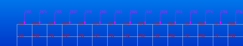
I would like to apply a variable distributed load to an edge of my model, something like this :

VirtualBox_windows_xp_last_edition_14_03_2017_20_47_10_a1si68.png


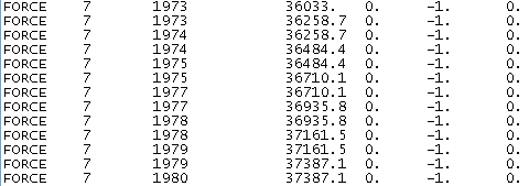
When I do the BDF the force is moved to the nodes but the problem is that values are not coherent at all :

VirtualBox_windows_xp_last_edition_14_03_2017_20_50_07_k8niau.png


If I want to make my own BDF not using Patran, how can I find this distribution ?
 
Replies continue below

Recommended for you

Hello,
your variable load in your first picture is just in a linear dependency, there is obviously regular increment 18 of units (I don't know if you plotted force per line or pressure...).
And you see in the second picture that the force is translated into bdf file for each node two times, I guess only nodes at the corners have only one card FORCE.
Therefore the node f.e. 1973 is loaded by force equaled to 36033 + 36258,7 Newtons (or whatever unit you used).

If you want to make your own .bdf file without any GUI, and your load distribution is linear, than it is very simple - just linearly interpolate (and node at corners extrapolate) values.
Example from your first picture:
element line between nodes 1979 and 1976 has value 2973.0; between nodes 1976 and 1977 is 2955.0.

Then node 1976 has force 2964.0 (minus half of increment).

And line in your .bdf looks:
FORCE,7,1976,,2964.,0.,-1.0,0.

and just add the rest.

But remember, it works only for uniform mesh. If your edge has variable element length then force cannot be linearly interpolated.


Regards, Jan


With best regards,
Dr. Jan Vojna
Lead Engineer Development

Siemens, s.r.o.
 
Hello,

I think that this make no sense because the force in the BDF is one order of magnitude higher than the Max force I applied (3000N). The first image show the force per line (I used a Distributed Load).

If I make the numbers as you said, I do not obtain the same results that there are into the BDF.
 
A distributed load is a load/per length, so you need to account for the width of the element (not just the number of nodes). The preprocessor automatically breaks down the running load (distributed load) into point loads to feed to the processor. You should be able to recreate this rather simply in Excel. The end nodes are loaded less than the interior nodes to create an equivalent distributed load.

You should probably start with a simple test case that has a constant running load (also equal width elements).

Brian
 
Status
Not open for further replies.
Back
Top