Continue to Site

Eng-Tips is the largest engineering community on the Internet

Intelligent Work Forums for Engineering Professionals

  • Congratulations IDS on being selected by the Eng-Tips community for having the most helpful posts in the forums last week. Way to Go!

Dividing a closing shell in half

Status
Not open for further replies.

drodrig

Mechanical
Mar 28, 2013
260
Hi there,

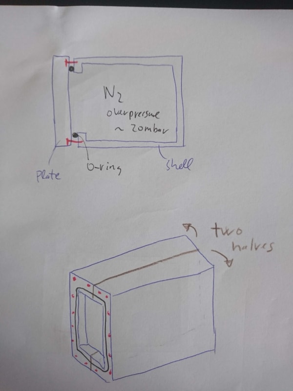
We have a closing aluminium shell. It is connected on an aluminium plate using screws and an o-ring. Inside there is a nitrogen atmosphere, overpressure, like 20mbar. We might change the shell to plastic. We have tested this, no problem.

We would like to divide the shell into two parts in order to ease the future maintenance.

What can we do to have 3 parts and be able to get them sealed? There will be a point where 3 edges join.

Here a sketch
DSC_0887_gc59q5.jpg


thanks
 
Replies continue below

Recommended for you

Something like this?

Regards,

Mike

The problem with sloppy work is that the supply FAR EXCEEDS the demand
 
Can you make your "closing shell" circular instead of square ??? --

Why is a square configuration required ?

(The answer: "because the client wants it that way", is not acceptable)

You could then put a threaded pipe cap/or pipe Flange on the end and gain full maintenance access

And your O-ring/gasket problem would go away ...

MJCronin
Sr. Process Engineer
 
Hi

I can’t see a split design like the sketch you have provided.
However I do have a question:- if the shell is solid then the only part Thing I can see that would need maintenance would be the replacing of the ring, so what inside the shell would need maintaining that creates the need to split it into three parts?

“Do not worry about your problems with mathematics, I assure you mine are far greater.” Albert Einstein
 
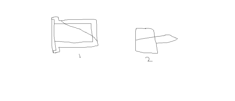
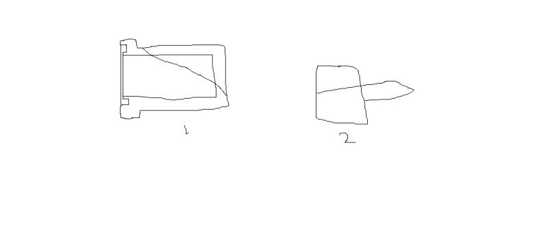
How about a diagonal split on the square box so the two sealing surface are separate? Note vastly improved O ring detail.

Or a 3d gasket (T shaped in side view) to replace the o ring and the separate seal.

sealing_y00ar4.png


Cheers

Greg Locock


New here? Try reading these, they might help FAQ731-376
 
Hi,

The Permatex could be an option, we will test it.

The overpressure will be for months. We have a pipe connected feeding in and one out connected to a bubbler (a bottle with water)

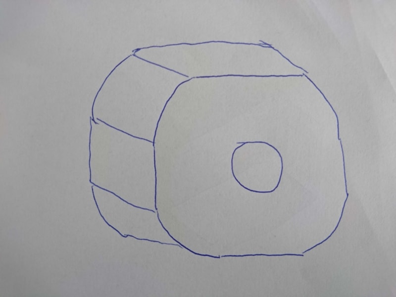
I simplified the design with our prototype geometry (and I had to draw it since I can't renew my licence because of the quarantine...). We will have a donnut like shape, with a hole in the middle where a pipe goes through. That's why we need to open it two halves on the sides.

The maintenance will be with the parts inside the shell. We want to make it "openable" to access inside.

Here is how it will look like. Maybe we could do it all round, but we need to open in half (the pipe going through doesn't allow to open it comfortably)
DSC_0888_j5ysql.jpg


cheers,
 
Hi Again

Instead of cutting the shell in two half's is it possible you can put cutouts on another two sides and use a oring sealed cover like you have on the front of the shell.

“Do not worry about your problems with mathematics, I assure you mine are far greater.” Albert Einstein
 
Hi,

We need the cap. It is a light closing shell attached (with he screws and o-ring) to a stiff aluminium plate which takes all the load of the things inside the volume.

Cut-outs seem an option. But we would like to completely remove the shell to access to the things inside. There might be modules to replace, electronics...

thanks
regards,
 
Sometimes you need to see the problem solving from the perspective of other professions.
What would happen if you change the shell to cylindrical similar to shell and tube heat exchangers? Internals can be attached to the cover and slide in. Flange can be external. This may solve all your problems unless you have limitation on the external dimensions.
 
Make an external shell that can be slid axially. It would have thw face seal of your current arrangement. The other end would have a diametral seal arrangement, a hole in the end of the shell mating to a round gland which stays in place with the base mounting plate. You would have to have enough clear space to move the shell axially to clear access for the internal component servicing.

Ted
 
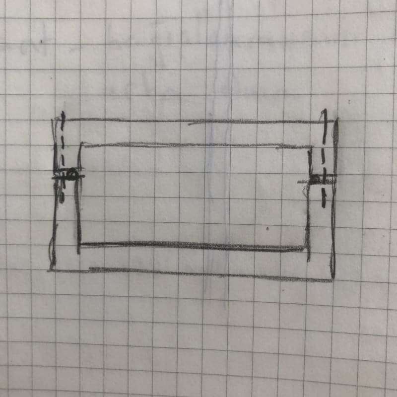
HTURKAK drawing has a solution, however, I would have two changes. First his "O" should be in a rounded groove. Secondly, instead of his bolting arrangement, I would bolt splice plates on the sides of the two half because his bolting arrangement could cause damage to the "O"ring. The bolts for the splice plates would have only partial penetration thru the wall thickness of the two half pieces. My thoughts.
 
Status
Not open for further replies.

Part and Inventory Search

Sponsor