Eng-Tips is the largest engineering community on the Internet

Intelligent Work Forums for Engineering Professionals

DIY crankshaft balancing with an oscilloscope 10

Status
Not open for further replies.

NDimitrov

Electrical
Sep 13, 2023
12
0
0
BG
Hi all,
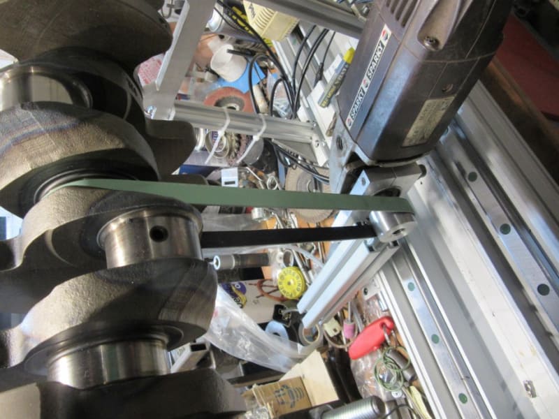
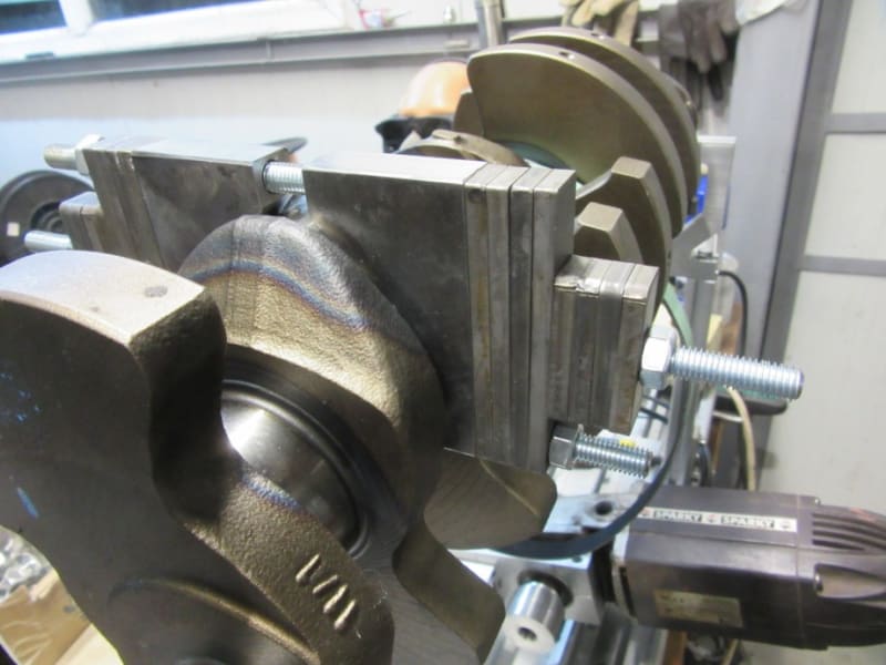
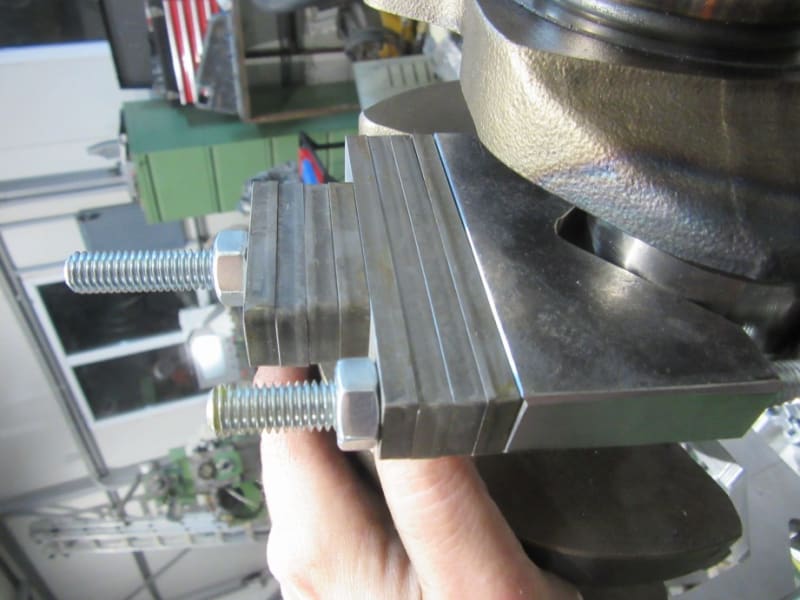
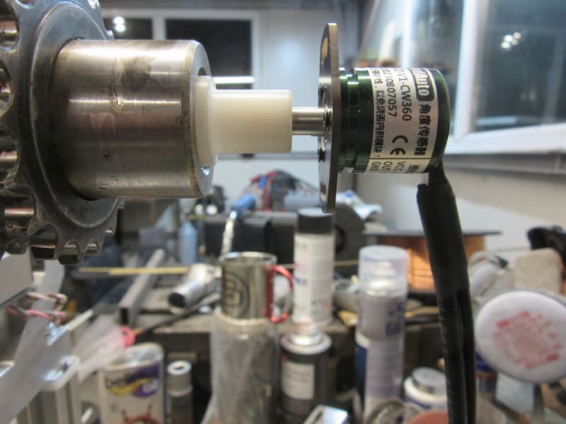
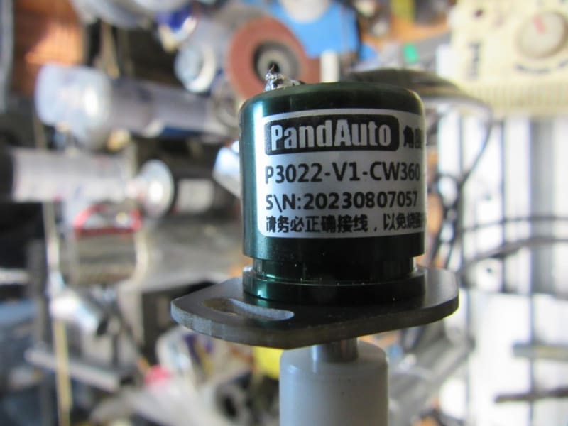
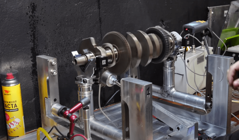
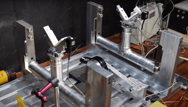
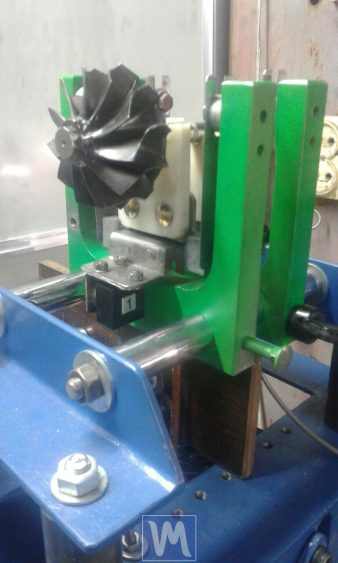
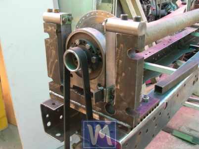
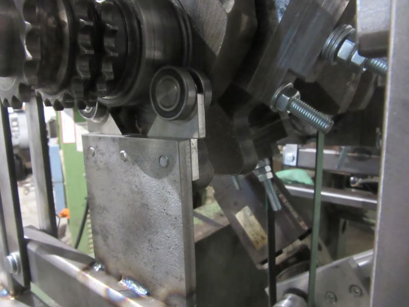
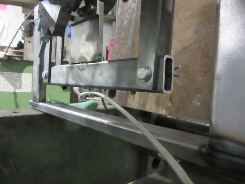
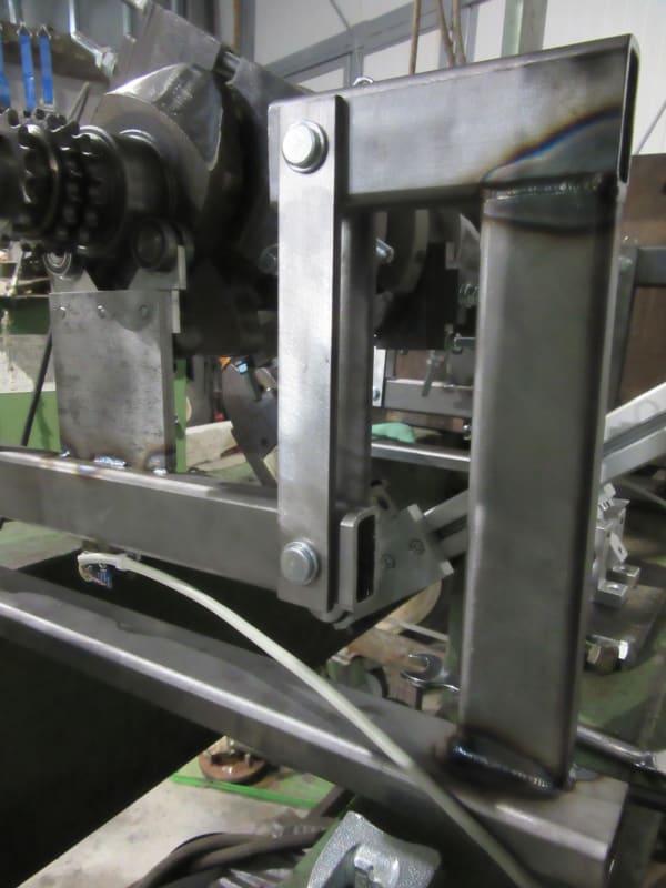
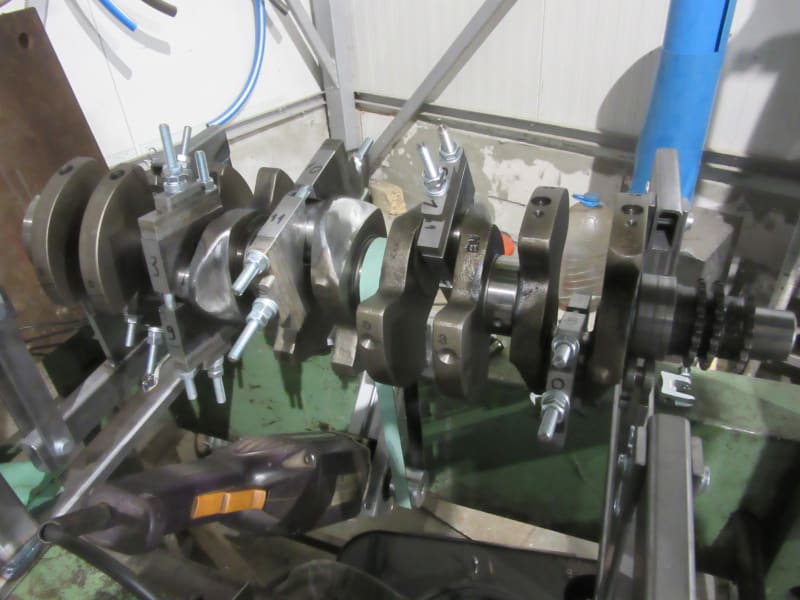
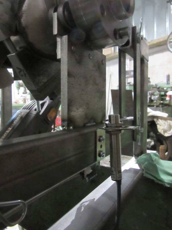
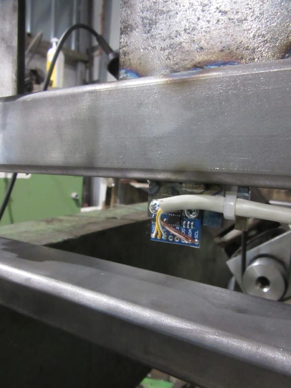
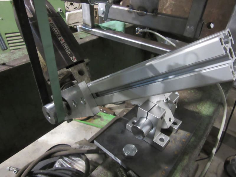
since I cannot find a local place to balance my crank I started to make a balancer stand using ADXL335 accelerometers and a QRD1114 looking at a reflective tape for triggering .
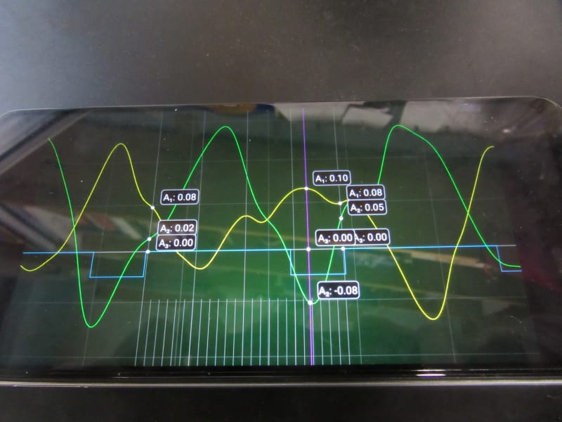
Finding the heavy spot using the acceleration plots is the easy bits .
I can't make the connection between acceleration and gr/cm imbalance .
Could somebody shed some light on that topic ?

Kind regards
Nikolai
 
Replies continue below

Recommended for you

OK, a bit of a delay but here is some progress .
IMG_0748.v01_pvhtks.jpg


IMG_0763.v01_gjktud.jpg


I got the halves to weigh equal (+/-0.2 g ).
I have the correction weights done as well .

IMG_0764.v01_fhqq3x.jpg


IMG_0762.v01_bcnrdw.jpg


IMG_0759.v01_bgdxkz.jpg


IMG_0757.v01_ycw19a.jpg


IMG_0758.v01_huri3s.jpg


IMG_0760.v01_rm5zpu.jpg


IMG_0761.v01_gjourj.jpg


The position sensor is a hall effect 0-360 degree 0-5v output sensor, in effect giving me an absolute encoder .

I'll get some play dough and do a dry run, this weekend, figuring out the light spots .

Cheers !
 
Good day !

Why did you decide to make a hall sensor and not, for example, a laser tachometer or an optical speed sensor?

I would make the struts shorter and the bands holding the support longer.

%D0%A1%D0%BD%D0%B8%D0%BC%D0%BE%D0%BA_%D1%8D%D0%BA%D1%80%D0%B0%D0%BD%D0%B0_%D0%BE%D1%82_2024-03-14_14-54-56_eozao5.png
%D0%A1%D0%BD%D0%B8%D0%BC%D0%BE%D0%BA_%D1%8D%D0%BA%D1%80%D0%B0%D0%BD%D0%B0_%D0%BE%D1%82_2024-03-14_14-56-09_sngmz5.png


Г-338w563h.jpg

Picture-4-402w302h.jpeg
 
Judging by your username it's no surprise you caught that right away. In fact there are two issues with my previous setup. One is the length of the arms, which in my second attempt is 150 mm (that gives a normal frequency of less than 7 Hz ). And the output of that adxl 335 is very noisy. The solution came from : Link . It uses Hscope app and is based on an esp32 which reads from two adxl345 sensors .
It worked like a charm . Only thing is you have to go by feel when it comes to how much to remove .
The whole setup is very easy to make with very basic tools .
IMG_0795_ih7ljh.jpg

IMG_0791_u5fni0.jpg

IMG_0787_wda6fi.jpg

IMG_0790_vk6hqg.jpg

IMG_0785_wvjmnx.jpg

IMG_0786_rkmyxm.jpg

IMG_0788_pgjrsb.jpg

IMG_0789_gvlgwo.jpg

IMG_0793_pzyexh.jpg

Edit : The small accelerometer pcbs work just fine with a clear cot on them. I found no good reason to build a case around them.
 
Status
Not open for further replies.
Back
Top