Eng-Tips is the largest engineering community on the Internet

Intelligent Work Forums for Engineering Professionals

DIY Shock Dyno 1

Status
Not open for further replies.

koushik123

Automotive
Dec 28, 2013
11
0
0
IN
Hi everyone

I am in the process of building my own shock dynamometer for racing applications. An overview of my design

1.Motor : 3 Hp,Single phase,220 v motor with a Max rpm of 3450
2.Mechanism : Slider crank mechanism with a setup to provide different stroke lengths ranging from 50mm - 200 mm
3.Load cell : Strain Gauge
4.Target damper speed : upto 500mm/sec
5.Speed control : Variable Frequency Drive

Please input your suggestions.
Help me with Data acquisition system as i am completely new to that stuff.


Thanks in advance

 
Replies continue below

Recommended for you

May I suggest, that you reconsider your stroke length. Unless you want to test Rally &/or Off Road Racing dampers 200 mm is quite a lot.
If you want to test these kind of dampers too, you would need to aim for much higher velocities as well.
To test for more realistic frequencies and learn a lot of interesting things in the process, you should consider much smaller stroke lengths as well. 50 mm is already "plenty" and I doubt you would need much more then 100 mm for a (road) racing application, but lower stroke lengths ( 2 ; 5; 10; mm etc. ) will teach you some interesting things.

v max = app. amplitude x omega which means that for 50 mm stroke you need only 200 rpm to generate a peak velocity of app. 523 mm/s this is a frequency of 3.33 Hz
With your proposed 200 mm stroke, you need only 50 rpm to do the same, resulting in a frequency of only 0.83 Hz

(note: my definition for stroke is the abs. distance from peak to peak. amplitude = 0.5 x stroke)

So you may want to look at including a gear ratio into your drive to get better torque/higher forces out of your dyno, and may also want to think about at which frequencies your damper will operate in the car/bike and then choose your stroke and rpm's accordingly to have a more realistic test scenario. ( mind about sprung and unsprung mass "natural" frequencies for example )
Contrary to common believe a "real world" damper doesn't generate force exclusively as a function of velocity, and this is where "all the fun" starts, when it comes to damper development.

As for the data acquisition. There is a general decision to make, do you want a time based system (sampling rate in hz) or a position/crank angle based system?
The former is a lot more common, but will generate more data points at lower velocities and never measure the force at exactly the same position. It's the most common method used, and if you choose the sampling rate high enough can work well.
You could look at any commercial PC based data logger system either USB or PCI card (for example which is quite economical.

The later (position based measurement) has the advantage that you have always the same number of data samples per crank revolution, independent of the velocity, and that the measurement is taken at the same position every time.
This is not such a big advantage when you start out, but later if you learn more about the inner workings of some "real world" dampers, you will start to appreciate the benefits of such a system.
In any case repeatability tends to increase with the later approach.
But as always it's "horses for courses" - what do you want/need, what are you looking at, how much budget you have, which compromises are you prepared to make etc.

Good luck
 
Hi TC3000

Thanks a lot for your useful reply..

By the way can you explain what different bearings should we have to use in this machine and how to select it??

We need bearings for
1.Conrod ( crank side)
2.Conrod ( slider side)
3.Slider

How to select these??

Well thats all i guess!! will i require bearings in any other places??


Well koushik123,
while I'm more then happy to help, were I can, I'm not going to provide you with a complete layout of an damper dyno, you will need to put some thought and effort into this as well.

Some things to consider.
Depending on what you want to do with this machine (you haven't eluded on to this much so far), you may want to first decide what kind of drive mechanism to use.
I know, that you said, you are going for a crank drive - which is fine, I just want to point out, that a crank drive dyno, will not produce a true sinusoidal (cos) function, but a so called scotch-yoke drive would. This in itself, isn't a big deal, just be aware of it, and based on your expectations/aim chose a appropriate stroke/conrod ratio, if you want to go with an crank dyno.

Most (not all) commercially available dynos these days make use of the scotch-yoke drive (unless they use hydraulic rams or linear drives, but this is a totally different class of dyno). To see the differences, you may want to have a quick look at these links.


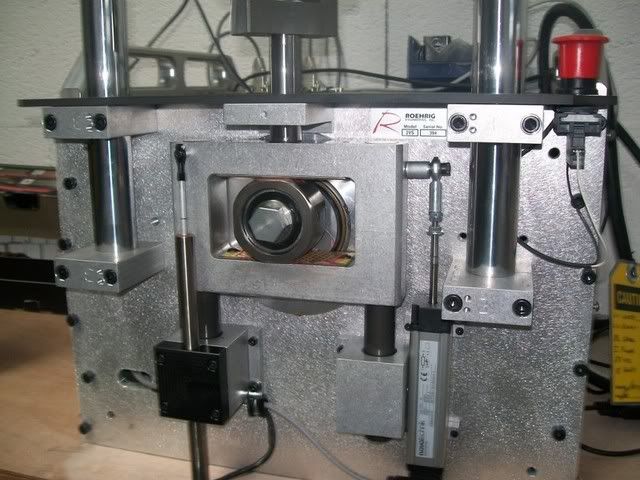
Here is a photo from a commercially available dyno, quite popular within the racing community, featuring a scotch-yoke drive.
Furthermore, you see the sensors for displacement and velocity in this photo.

100_1482.jpg


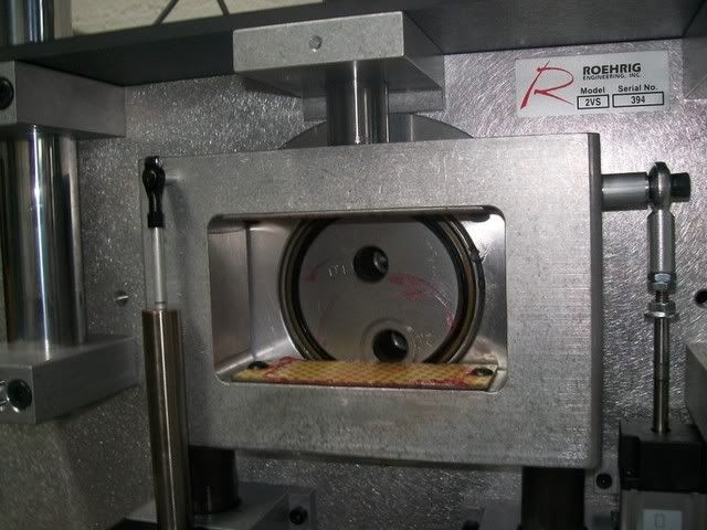
detail of the scotch-yoke

100_1483.jpg


now coming back to your question:
As always it depends on what you want to do, what you have at hand and what your budget is.
You need to have an idea, which forces your damper is going to produce and then chose a appropriate bearing size.
If you want/need to build a really low cost dyno, you could go and use an old conrod from an engine and the piston pin as well, so you would have one side of the crank mechanism sorted out.
I would use roller bearings for the conrod to crankshaft and conrod to slider attachments. Nothing fancy, just double sealed roller bearings of an appropriate size. ( I know, that you can make an argument, that this is not the best arrangement for the conrod to slider connection, because the bearing will not make a complete turn, same argument as for suspension rockers, nut I will leave it to others to argue this case. I know that it works on a practical level)

As bearing for the slider, you can either choose a plain PTFE bearing, like you find in most McPherson upside down struts or motorcyle forks ( - low cost option would be to use a Bilstein 40 mm strut/damper tube with the assorted strut bearing (get for a couple of bucks from your wrecker) or similar

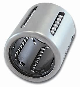
or, and that would be my choice, and is quite common in commercial dynos, these days use a "linear bearing" complete with assorted hardened guide/bar.
Keep in mind, that if you use a linear (roller) bearing, your slider needs to be hardened, otherwise it wont last long. But you can buy this "off the shelf" - no big deal/cost today.

Linear_Ball_Bearings.jpg


As I said before, it's not very common, to mount the crank drive directly onto the motor. Most dynos, will either use a "gearbox" - not many or and this is a very common layout use a tooth belt drive to drive the main "crank-shaft".
Therefore you would need at two (roller) bearings more for the shaft - nothing fancy.

Other thinks to consider.
Try to use a "low displacement" load cell (pancake type) vs. an S or Z shaped one. (it's a bit more expensive but worth the investment - IMHO)

If you are pedantic, consider to mount the displacement (and velocity) sensor(s) parallel to the damper/shock you test, if you want to measure "true" damper/shock displacement/velocity. (most dynos measure only slider displacement/velocity)
Otherwise the deflection of your load cell/load frame may create an error in your measurements.
How large this error is, depends on the quality/integrity/stiffness of your dyno --> see comment on the load cell recommended, and what you are trying to do with your dyno, what is important to you.

This becomes more an issue with low stroke/high frequency measurements/analysis.

good luck
 
o.k. - I know, that this isn't a damper/shock dyno
Nevertheless, it shows a quite typical "drive" application

motor --> belt drive --> (crank) shaft, which is supported by two off the shelf pillow blocks with roller bearings.
Something like this, is used in many damper/shock dynos too
You can then use an incremental decoder on the (crank)shaft if you want to go for an position/crank angle based measurement system.

new-dyno-room-02-c.jpg
 
Good informationn from TC3000. Just to stress one point - as TC3000 mentions - make sure you instrument to look at what the damper is really achieving in terms of velocity. Motor RPM and stroke are not at all adequate to predict it.
 
Status
Not open for further replies.
Back
Top