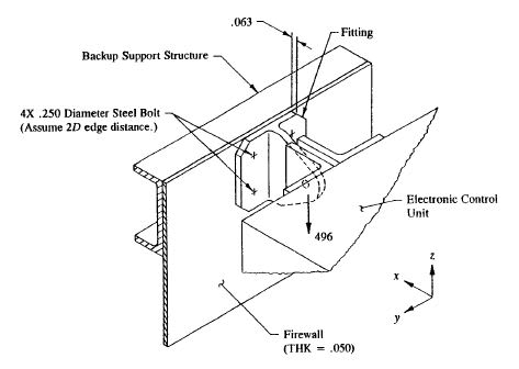
Lets say I have a structure with loading as shown in the below figure.

My understanding is along the line of what Flabel says in his book. I am posting excerpt from Chap. 5 "Shear & Tension Clip Supports" Example 5-6, Page 349-350.
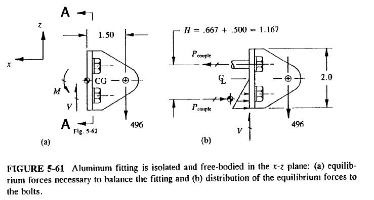
Image illustrating the FBD as Flabel draws it.

A couple of days ago, I was asked in an interview a question along the above lines i.e. how best to transfer moments between two structures. Although, I did not think of this joint arrangement, the interviewer brought this up and I guess he was expecting to hear my knowledge about moment load path. Two plates joined by 2 rows of bolts, subjected to an end transverse load.

I gave the above answer i.e. the "compression" part of the couple will be transferred through bearing contact of the plates and bolts won't transfer it. He disagreed and I mentioned I got this info from Flabel's book but he did not seem convinced. He maintained that bolt will carry the compression part of the couple and my scenario plays out if there is only one bolt (to carry tension) and the compression part will be carried via "Heel-Toe" effect between plates.
Anyways, I am posting here to get clarity on my understanding. What do folks think about bolt carrying compression in a joint like above? I plan to do a 2D FE analysis with CBUSH Springs (bolts) & Contact between plates some time in the next week to see how FEM reports the load path.
Regards...

My understanding is along the line of what Flabel says in his book. I am posting excerpt from Chap. 5 "Shear & Tension Clip Supports" Example 5-6, Page 349-350.
The bending Moment M determined there (that is, at the centroid of the fastener pattern) is further distributed as a horizontal couple-force between the upper bolt attachments and the lower base flange portion of the bracket: one force acting along the centreline of the upper bolts and the other acting along the center of bearing pressure of the lower base flange, as shown below. The contact stresses depicted in this figure are referred to as bearing stresses, not bolt compression forces. Hence, the lower bolts do not actually carry this load. Here, the bearing stresses are entirely carried by the lower base flange.
Image illustrating the FBD as Flabel draws it.

A couple of days ago, I was asked in an interview a question along the above lines i.e. how best to transfer moments between two structures. Although, I did not think of this joint arrangement, the interviewer brought this up and I guess he was expecting to hear my knowledge about moment load path. Two plates joined by 2 rows of bolts, subjected to an end transverse load.

I gave the above answer i.e. the "compression" part of the couple will be transferred through bearing contact of the plates and bolts won't transfer it. He disagreed and I mentioned I got this info from Flabel's book but he did not seem convinced. He maintained that bolt will carry the compression part of the couple and my scenario plays out if there is only one bolt (to carry tension) and the compression part will be carried via "Heel-Toe" effect between plates.
Anyways, I am posting here to get clarity on my understanding. What do folks think about bolt carrying compression in a joint like above? I plan to do a 2D FE analysis with CBUSH Springs (bolts) & Contact between plates some time in the next week to see how FEM reports the load path.
Regards...
