CivilEngineer401
Civil/Environmental
Does anyone know a good way to figure out the head loss through a weighted check valve in a sewage pump station?
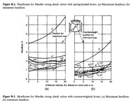
Most of the pump stations I work on have weighted check valves on the discharge line. We typically install them because operators like the visual confirmation when the pump is running, and they provide a way to hold the check valve open if needed to empty the forcemain back into the wetwell.
The problem I’ve encountered over the years is that there always seems to be a discrepancy between the actual flow of the pump station and my calculations. My theory is that the weighted check valves might be the cause.
Typically, I use a K value of 2 for the head loss coefficient for a 6” weighted check valve. However, I’m starting to believe that the “K” value might be much higher than typical when the valve is barely open (e.g., at flow velocities of 1 or 2 ft/s), potentially exceeding 10. When we turn the VFD up to full speed and the valve opens more, resulting in higher velocities (e.g., ~7 ft/s), the K value seems to drop back to a more typical value of around 2.
Since I don’t typically account for different K values at varying flow velocities, this variation may not be reflected in my calculations. What do you think? Could this explain the discrepancies I’m seeing?

