Continue to Site

Eng-Tips is the largest engineering community on the Internet

Intelligent Work Forums for Engineering Professionals

  • Congratulations waross on being selected by the Eng-Tips community for having the most helpful posts in the forums last week. Way to Go!

Do you show flanges on a plant P & ID? 18

Status
Not open for further replies.

LittleInch

Petroleum
Mar 27, 2013
21,346
Ok, we're having a debate internally here about what is "normally" done on a P & ID.

Do you
A) Show deliberately a little vertical line next to each flanged valve to indicate it's a flanged valve or
B) Assume all the valves in a plant are flanged valves.

If B how do you show when it is deliberately a welded end valve you want (e.g. last valve going into a long gas pipeline)

I've seen both ways and A really annoys me as you get little lines all over the place and then you can't see it or it gets lost in all the other data.
We're talking fairly basic P & IDs here, not the all singing all dancing "intelligent" P & IDs.

Spool pieces, blind flanges on e.g. drain valves are shown but "normal valves"?

Answers on a postcard please....

Thanks, LI

Remember - More details = better answers
Also: If you get a response it's polite to respond to it.
 
Replies continue below

Recommended for you

Hey Snorgy, we're in alignment on just about everything EXCEPT showing every flange. Perhaps if you use the proviso, "...on every line greater than 2" NPS", your rule about flanges might make sense to me. But I've never had a client who insisted on this.

Not to compare resumes with Snorgy, but I've been working and living in Canada a long time too, though most of my projects aren't in Canada. It's just another piece of evidence that skilled and competent people can hold strong, and divergent, opinions about the only right way to do something, and yet there may be more than one "right" way.

I'm curious what do you do with the other types of couplings or joints that give someone access to the process fluid? Do you show compression fitting joints? Threaded unions? Victaulic couplings? Tri-clamp connections? Our piping systems aren't all piping, and when they're piping, it isn't all flanged... We follow the same rules with those connections as we do with flanges: we show them when they're needed to understand function, and don't show them otherwise unless a client insists.

FYI I never said that a P&ID isn't a fabrication drawing: I said that it is neither a routing nor an isometric, which is pretty obvious. When flanges ARE on our P&IDs, it's a signal to our piping designers to ensure that they're present- because they have a necessary process function.

Your comment about the minimum level of competence of people drawing P&IDs resonates strongly with me. Too many people attempt to eliminate the need for basic competence in the design of pressure retaining equipment by replacing that competence with pipe specs. We see that in many of our clients and we find it both frustrating AND dangerous.

 
As BigInch posted, if something is important, show it, however it usually is not necessary to show flanges.

Fabrication drawings, also called machine drawings, are principally found in and around machine and fabrication shops where the actual machine work is performed.

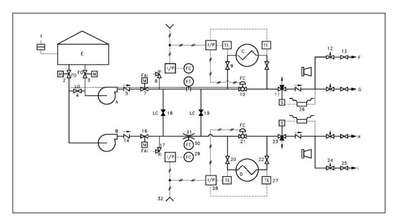
P&IDs are usually designed to present functional information about a system or component. Examples are piping layout, flow paths, pumps, valves, instruments, signal modifiers, controllers, etc:

Document153_qsdocx.jpg


P&IDs do not have a drawing scale and present only the relationship or sequence between components. Just because two pieces of equipment are drawn next to each other does not indicate that in the plant the equipment is even in the same building; it is just the next part or piece of the system. These drawings only present information on how a system functions, not the actual physical relationships.

Because P&IDs provide the most concise format for how a system should function, they are used extensively in the operation, repair, and modification of the plant.

From Department of Energy Fundamentals Handbook

ENGINEERING SYMBOLOGY, PRINTS, AND DRAWINGS


For those things that are deliberately left off P&IDs for the sake of clarity, other documents are used to provide the details. Common documents that serve vital support functions to P&IDs include:

Piping and material specifications. Here, you can dig into all the gory details about materials of construction, gaskets, bolts, fittings, etc. for each of the services.


Examples of PIDs':

"If you compare lead sheets from a few dozen companies, you will find that 90% of them are pretty much Copy | Paste. For that last 10%?, there can be distinct differences and company-specific conventions used that are not obvious on P&IDs."

"Clearly there can be a lot of information to show on a P&ID. And for this reason, there are various degrees of detail that a particular company will generally choose to show. There is no formal standard for the various amounts of information a P&ID must include. Rather, it is left to the discretion of the engineers involved. In terms of detail provided, my opinion is that a good P&ID will strike a balance of "clarity without confusion". If you can't see the process for all the symbols, then it's probably overdone. On the other hand, if you can't even discern how a pump may be operated or what interlocks may exist, then you probably need to embellish it a bit."
 
Dear Snorgy, I value your opinion however, would like to highlight how it is done.

I strongly believe that P&ID can't cover all the items which are required to fabricate the line at site otherwise why Piping would consume so many hrs to generate all the deliverable like Plot Plna, Equipment Layout, Piping GA, Isometrics, Material specifications.

Pls reconsider your opinion considering all the inputs being received in this topic.

P&ID just can not cover all the items.

Example- If there is Epoxy lined Piping & the lining requirement is to have flanged connection every 12m. This is doesn't mean P&ID will cover all these flanges for say some 200m of run of this lined piping. Does that makes sense?

Thanks & Regards,
Abhijit
 
In my opinion, all flanges should be shown on P&IDs (Piping & Instrumentation Diagrams). Snorgy's commentary is spot on. The P&IDs are the bible and are the foundation for all other construction/fab drawings.

We also typically label the class rating (e.g. 150#, 300#, etc.) on every or flange joint in our P&IDs, just for the sake of consistency. It's amazing how often contractors or clients will mistake spec break locations.

On PFDs (Process Flow Diagrams), showing flange symbols would be extraneous and are never shown.
 
Consistency is a good reason not to show all details on P&ID's. If the same item is needlessly shown on multiple drawings, it is a headache to have to go through the entire set of drawings to make sure that everything is consistent throughout the set.


Hi,

Not all flanges are required to be shown in the P&ID. If a flange is used as a mechanical joint to connect two pipes, it need not be shown in P&ID. Flanges connecting to equipment (which includes valves) are to be shown clearly in P&ID; adopting a legend which can discriminate a welded valve to a flanged valve can solve the purpose.
 
WOW,

I only expected 4 or 5 replies, not 45, so many thanks to all those who have contributed here to a very interesting exchange of views.

I've flip flopped a bit reading some of these comments, but finally gone back to my start point, which is that, all things considered, showing flanged valves as flanged valves on a P & ID is ultimately easy for a CAD designer, even in simple P & ID blocks, never mind the new intelligent ones, prevents you having to check valve tables and piping specs which may or may not tell you whether flanged valves are used and is useful during piping drawings, fabrications and operations.

Yes, you always need to have the legend sheet available, but showing flanges at flanged valves, which is where this post started, to me now seems to done by enough people with good reasons why to make it my default, if I actually have control of the legend sheet - which isn't always the case.

Someone said if I had a spool which was broken into flanged section to allow easy removal or needed for manufacture then yes, I would either show all the flanges or show one spool piece then add a note saying "multiple ( or 20) spool pieces installed in this section". At the very least when you're doing a HAZOP it will highlight the potential for increased leakage or break / make issues if it is dismantled during some operation, say a well work over.

Thanks again for the info and conversation and feel free to get the half century of responses
LI


Remember - More details = better answers
Also: If you get a response it's polite to respond to it.
 
You need to remember WHEN a P&ID is generated, and for those that don't know it's at the beginning of the project(or suppose to be). Remember that a P&ID is a SCHMATIC and is NOT used to indicate real-world piping configurations. SO how would anybody generating a P&ID know where to put flanges or unions (other then connection points on "store bought equipment" or generically between two points to indicate a piping spec change) which aid in construction or maintenance of a piping configuration!?? So now your doing an as-built walk-down of a brand new facility, WHY would you note a flange on a header, where for what reason (other then a piping spec change)the welders decided they needed one to aid in piping assemble? You wouldn't see any recognizable configuration to even show where the flange was on a P&ID. Best you could show was it's between two know pieces of equipment, what good would that serve? Adding "extra" stuff to a P&ID is confusing, time consuming, not necessary, and a waste of man power and money. ...And 30 years ago wouldn't be an issue, only now with the know everything computer experts are these "extras" required. ...My $0.02
 
11echo,

P & IDs are more commonly produced towards the start of FEED, but then checked, amended and added to over the life of the project, especially as more information becomes available from e.g vendor data, more analysis is undertaken and more data added.

I disagree with your statement " a P&ID is a SCHMATIC and is NOT used to indicate real-world piping configurations". Sure it doesn't show all the elbows, bends, turns etc, but if it shows one take off of a certain size or branch of a different size then a valve then a piece of equipment, that's the order the piping has to follow.

The original question was about showing flanges on valves and then it sort of mutated, but as per my summary in the last post, on the balance of responses and the ease of doing it, showing flanges seems quite reasonable to do.

If a welded decided to add a flange that wasn't shown on a drawing I for one would be very upset...

You're entitled to your opinion and doing it that way - there seems to many others who would do it a different way and that's fine also.

Remember - More details = better answers
Also: If you get a response it's polite to respond to it.
 
LittleInch, do you think that all flanges should be shown when they are used to interconnect shop-fabricated, field-erected plant modules to each other?

And I agree that "a P&ID is a SCHMATIC and is NOT used to indicate real-world piping configurations". To me "real-world piping configurations" means just that - what the piping looks like in the field when installed.

"...it shows one take off of a certain size or branch of a different size then a valve then a piece of equipment, that's the order the piping has to follow.". Well of course; I don't think anyone said that wasn't the case.
 
Gator,

Yes I do.

Maybe real world piping configuration is being misunderstood here. Clearly it is a schematic, but said schematic can show all relevant parts such as flanges, drains, vents, branches etc etc. It quite often says things like minimum distance, vessel heights and sizes.

Plus this post has now made it to 50 replies ;_)

Remember - More details = better answers
Also: If you get a response it's polite to respond to it.
 
Hi Everyone,

I do agree with Snorgy 100% on this. I'd like to share few points on this.

1. P&ID is "living" document. It will be revised, added or changed not only throughout of the construction project, but many years after completion of the construction. The plant owner will maintain all systems and equipment, add/remove/upgrade/replace them as time goes by. Obviously, P&ID will be revised and re-issued every time there is change.

2. Having shown all items in P&ID will be handy in those circumstances I have mentioned above. If you working on a maintenance project to replace some plant equipment, knowing flanged connections will help to plan your isolation points accordingly.

I know you may not know everything in the system, and still do your job. Knowing is better then not knowing...

Regards,
Curtis
 
"2. Having shown all items in P&ID will be handy in those circumstances I have mentioned above. If you working on a maintenance project to replace some plant equipment, knowing flanged connections will help to plan your isolation points accordingly."

I agree. But P&IDs are not always kept up to date (the reasons for P&IDs not being up to date can be numerous) and there's no way to be sure of what's there without a site visit. Imagine assuming flanged tie points are there because they exist on the P&ID and then finding out you have to perform hot work.

Perhaps owners' commitments to accurate as-builts has improved over the years.
 
Gator,

I think Owners' commitment to as-builts has gotten progressively worse since I started in 1981. Unfortunately, the expectations of Regulatory bodies in my geographic region(s) has moved in the entirely opposite direction to that trend. The EPCs I subcontract to now all want to START with a good set of Client as-builts, and if they aren't available, they book a trip to the field to create them from the last best known version of the drawings. Invariably, the sites (brown field) are not exactly "as-built", so the P&IDs start off with red right off the top. Then, prior to start-up, after all of the design modifications have been made and the project has been "built", everything is walked down and a new set of "as-builts" is spawned.

Then the Client and others do...other things...that don't get documented, like add control valves, change line sizes, install compressors...and a new EPC contractor comes along and begins to question the competence of the predecessor.

The best you can do is, "When the project started, the site (within scope) looked like this; when the project was over, the site (within scope) looked like that."

The things I do, when it comes to as-builts, I show every flange I see.
 
Hey Snorgy, we started in the business the same year.

I keep hearing great things about laser scanning for as-built piping but have no idea of the cost.


Status
Not open for further replies.

Part and Inventory Search

Sponsor