Continue to Site

Eng-Tips is the largest engineering community on the Internet

Intelligent Work Forums for Engineering Professionals

  • Congratulations KootK on being selected by the Eng-Tips community for having the most helpful posts in the forums last week. Way to Go!

Does design of lifting lug have some standard practice? 2

Status
Not open for further replies.

behanan

Mechanical
Jun 10, 2019
13
I have a vertical vessel of 5000mm ID , whose top end is elliptical head and bottom head is conical, with cylindrical shell attached in between. The weight of the vessel is 18tonnes. What will be the maximum thickness of the lifting lug ?
 
Replies continue below

Recommended for you

Suggest you take a look at the R002 Norsok Lifting Equipment document as guidance/reference.
 
In my opinion there is no single "standard practice" that covers the design of lifting lugs (padeyes) for pressure vessels.

ASME VIII contains no specific set of rules for designing the lug .... ASME does, however place restrictions on the selection of acceptable materials, the welding requirements and the inclusion of the welded lug at the time of vessel hydro.

NORSOK, NASA, several companies and individuals all have developed proven guidelines for lifting lug design. Search "eng-tips" for many threads about this topic.

I would like to hear the thoughts of others on this topic

MJCronin
Sr. Process Engineer
 
You may want to review DIN 28085 and/or DIN 28086.
Not sure if the PIP standards also might have something for this.
 
Read UG-54(a)if designed to ASME Section VIII Div. 1, All vessels shall be so supported and the supporting members shall be arranged and/or attached to the vessel wall in such a way as to provide for the maximum imposed loadings (see UG-22 and UG-82).

Test Weight.
 
Have you reviewed ASME BTH-1 (Below-The-Hook lifting devices)? I believe it covers lifting lugs.
 
BTH-1 doesnt cover what youre looking for. The OP is looking for a lug (assuming welded to a vessel), whereas BTH is for devices which are under the hook. A lug is not a device, but an integral part of the vessel. It would be strange that BTH would cover lugs; consider you have a vessel which is finished and needs to be lifted. Someone takes BTH at hand, and then finds out the lugs on the vessel dont meet the BTH Code requirements. That wouldnt make sense.
 
Why not use trunnions?
My previous response to a similar question:
IMO working with an experienced good engineer who has done this type of work time and time again in the past without issues is my recommendation.
Books and theorey are all good but books do not cover all the things you may come across in reality.
 
See "Pressure Vessel Design Manual 4th Ed. Dennis R. Moss and Michael Basic"

Regards
 
'' pressure vessel handbook '' by Eugene F. Megyesy may help full too
 
I use the aforementioned Denis Moss myself. But you don't necessarily have to buy it. I allow fabricators to use any method that is based on sound engineering and takes account of all of the below...
(Other manufacturers' in-house methods will essentially all follow the same basic Good Engineering Practice.)

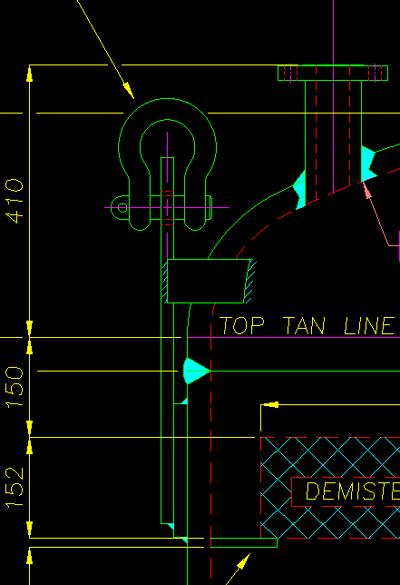
Check shear through the shackle hole; shear in the proposed shackle (or you could consult a catalogue); shear in weld; bending in lug and bending in the weld. If there is a doubler pad check shear and bending in the weld and bending in the plate (a bit nebulous that one). Use a snatch factor (2.0 would be good). And make sure you design for the full lift (e.g. horizontal to vertical). Make sure you know whether the vessel is to be lifted dressed or not. Lugs will always also be subject to a certain amount of 'lateral' stress (into or away from the vessel) especially if no spreader beam is used, so it should be taken account of, even though it will be a bit of guesswork. Use WRC 107 (for manual calcs - WRC 537 if commputerised) to check the local loads on the shell.
 
Litfing lugs -or trunnions- in pressure vessel shall comply with ASME BTH-1 Design of Below-the-Hook Lifting Devices, where the nominal design factor Nd= 2 (min.) for category A.

Regards
 
Lifting lug / trunnion shall pass a load test before hydrostatic test.

Regards
 
Afaik, there’s no mention of BTH-1 in VIII-1.
 
r6155:
Where in ASME BTH-1 or even in ASME B30.20 does it mention the design of pressure vessel lifting lugs or trunnions? I cannot find this.
Also - please let me know how you load test lifting lugs and trunnions, say for example a 40m long column (130feet) weighing say 100Ton.
It is not practical and I have never seen load tests done on pressure vessels or columns.
The design is proven and NDE applied both in the welds and in the vessel or column plate.
 
Look at procedure 7-6 from the Pressure Vessel Design Manual by Dennis Moss.

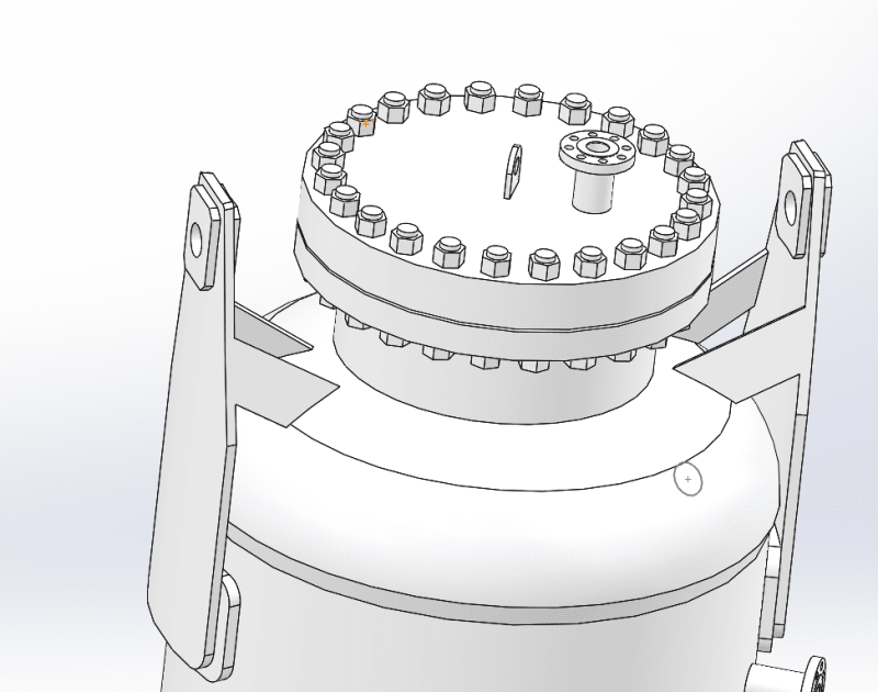
Sometimes using lifting trunnions instead of lifting lugs might be a better idea because the lifting lugs have several issues:

If they are welded to the top head - they can be affected by forces perpendicular to their major plane - i.e. relatively easy to bend or break them.
So the usual practice for lugs of many plants is to have them welded to the shell which usually makes them very long so extra gussets need
to be incorporated in the design to keep them rigid. (I am attaching examples).

If you're not allowed to grind flush the circumferential seam under the lug or weld perpendicularly through it for some reason,
then a compensating pad becomes mandatory. Sometimes the heads could be thicker than the shell and you would need a pad too.

Lifting using the shell cylinder reduces the risk of deforming the head. You would also need to check the stresses in either of them (depending on which approach you use)

Another option is to have the lifting lug welded to a temporary flange cover as shown here:

but this is rarely used.

Vertical vessels are usually lifted in place using two cranes. So you'd need two lifting lugs at the top and a tailing lug somewhere in the lower section of the shell cylinder or the cone
in order to execute the lift properly.

All lifting devices should be checked for lifting from horizontal to vertical: 0 deg to 90 deg orientation.

Also the minimum typical safety factor for on-shore applications would be about 1.5. SF=2 and above should be considered for off-shore applications.

If this is an actual job and you're not sure what you're doing - ask someone with experience to show and explain. Lifting devices are critical.

Untitled2png_vzwnyh.png


Untitled_wpa1pr.png

 
CuMo, excellent post. Just a small remark; please remove the link to Moss' book, even though it's on Google and youre not physically sharing it; youre still directing to copyrighted materials. That's not allowed by the site. Apart from that, a star for you.

/edt: BEHANAN - are you actually reading this? You seem to make some dubious posts, but (so far) never reply to any of them. Whats your intent with these questions?


... and of course, the thieves at scribd.com have been busy by stealing and selling the knowledge of others ....


It has become much more difficult to find authentic and valid technical papers since these thieves (yes i said that) have set up shop ....


MJCronin
Sr. Process Engineer
 
BEHANAN, as r6155 mentioned, I'd recommend you to follow "Design manual 4th edition by Dennis R Moss" its one of the widely recognized book with detailed and comprehensive methods for Design/Analysis. And, don't forget evaluate the stress induced on shell / head due to rigging / lifting loads. In case of horizontal lifting, you'd also have to evaluate the bending stress at the center of shell due to rigging / lifting.
 
I speak about load test. Design calculation is clear in the books.

See
Lifting Operations and Lifting Equipment Regulations (LOLER) 1998: Open learning guidance
Regulation 4(b): the load being lifted

This part of the regulation is about ensuring that the parts of the load that become connected to the lifting equipment during lifting operations are sufficiently strong. Examples are lifting lugs welded in place to facilitate lifting, jacking or lifting points.
You need to know that:
- lifting points form part of the load;
- routine checks need to be made of the condition of lifting points;
- it may be appropriate to test the strength of lifting points such as welded lifting lugs.

Examples of lifting points include:
- lugs that are welded onto a steel beam before it is lifted, and that are removed afterwards;
- permanent fittings such as those on a skip which may often be lifted.
Key terms
Part of the load: Includes anything which connects the load to the lifting equipment and is lifted.

Regards
 
Status
Not open for further replies.

Part and Inventory Search

Sponsor