Eng-Tips is the largest engineering community on the Internet

Intelligent Work Forums for Engineering Professionals

  • Congratulations waross on being selected by the Tek-Tips community for having the most helpful posts in the forums last week. Way to Go!

Does this use of multiple datum features make sense? 9

Status
Not open for further replies.
Replies continue below

Recommended for you

CH said:
How exactly are you going to check features A and B against A-B and how it will be different from what is already shown on 11-18?

Now if we look at OP case, how datum / feature / simulator for A-B will look like? It isn't the common axis of A and B, isn't it?
I would say my hypothetical case A-B planar datum features will have the same mathematical definition as the case shown in the standard. No differences, as far ad I can see. The fact you would have practical limitations during inspection does not forbid and imply that the scheme is not valid and functional correct.

The OP case is no different. Two perfect datum features simulators, basic distance apart and also basic angle apart (because they are not in the same plane) and the DRF is obtained from those simulators.
Am I too far in the theoretical weeds?
 
geenimi - the problem with the two axes is that they each control 4 degrees of freedom, which is 2 two many, even in the nominally parallel degenerate case. The limited examples in the standard don't generate that sort of problem.

However, most the the examples in the standard are handouts to CMM operators. A physical fixture can be made to have the exact datum simulators per the original drawing. The CMM operators have problems doing the surface fitting required to handle odd cases like this.

---

In that very good example pdf, the location of "B" is highly leveraged by the length of "A". If that part were 20 feet long, then only the most perfect of perfectly formed parts would match - all others, very likely useful, would end up in the garbage.
 
One more example for your reference, you may find out some more from SAE-J2370
(Geometric Dimensions and Tolerancing for Curved Hose)

2021-08-13_140455_yv7teo.jpg


Season
 
Thank you Season.
I knew I've seen the concept somewhere, in some training materails or some commerical books.
Maybe you even posted here before.
Thanks again.
 
Note that they skip the bends, which apparently have no tolerances. There's also the minor question of whether datum feature A and datum feature B are only at the intersection with the planes or apply to the entire surface. I'm sure there is some other detail about how there is a transition from dia 20 to dia 21 and back and what the ID/OD is where it is omitted along with the molded collars. I know - incomplete to add confusion.

I am impressed that they are expecting to hold the position of a pair of molded hose ends with 0.5 mm without restraining it.

Is there a definition in that document of what a Geometric Dimension is? Such a definition was never part of any version of Y14.5
 
SeasonLee,

Your example also is over constrained, unless we treat it as flexible, and call up some maximum force needed to constrain the datum[ ]B feature into its nominal position.

--
JHG
 
Two skewed cylinders over-constrain movement. Datum feature C increases the overconstraint by one or two or three, depending on one's decision to count them individually or with the "ignore the ones the inspector doesn't like." Technically it implies the coordinates of the tube are measured from the datum feature simulator and that requires contact with the datum feature which may require bending the tube to fit.

ASME needs to get their stuff together and establish a surface deviation boundary which would control this explicitly rather than the additional stuff of adding and subtracting and overworking the position geometric characteristic in ways that are difficult to apply, such as in the bends.
 
3DDave,

Long, bent tubes are flexible. ASME Y14.5 describes how to apply datums to flexible features, and I find this feasible and practical.

--
JHG
 
I worked on a system with dozens of 20-25 foot long hydraulic lines with up to 15 bends to do tolerance analysis based on LRA data from the bender to compare to FCF specifications so I know that all too well, which is why I know these examples are so obviously poor. The examples given are not treated as flexible features. That would include limiting of the forces and specification of locations to apply them allowed to get the parts to conform to the specified limits. It's also pretty tough to manage that on CMMs.

The examples are another "tossing constraints at the problem and hoping someone else can figure it out" as I mentioned before. They look great as long as one is willing to either over specify the manufacturing process and pay more than what is required for excess precision or to toss out parts that are usable but don't happen to fit the narrow definitions.
 
CH said:
The situation we are talking about is called "Multiple Datum Features" (2009) or "Common Datum Features" (2018).

In both standards datum produced from MDF / CDF can be:
Single Datum Plane
Single axis of Two Coaxial Features.
Pattern of features of Size at MMB
Pattern of features of Size at RMB
So, no, two planes basic distance apart will not cut it. Same with two axis distance / angle apart.


CH,

I know you are well-versed in ISO (more than me), but the discussed practice is legit in ISO GPS too.

ISO 5459:2011

C.2.6 Two parallel planes
Figure C.33 illustrates the drawing indication of the design intent.
Design intent (writing input)
Use two integral, nominally planar and parallel surfaces, which are not features of size, simultaneously to establish a datum with a constraint of distance between the two planes. The datum is used to orient and/or locate the tolerance zone relative to a plane. This plane is the situation feature of the collection of the two associated planes which are constrained to be parallel and separated by a value indicated as a TED.

A and B being used as two parallel planes
 
Not sure if this is the snag but "In both standards datum produced from MDF / CDF can be:"

That isn't the same as "datum features used as a basis for."

The resultant of an MDF or CDF is not two separate planes or two separate skew axes.
 
Question to the experts:

Part1_yk7cra.jpg


Is this legitimate control?

If no, why?

If yes, how datum / feature / simulator looks like?

"For every expert there is an equal and opposite expert"
Arthur C. Clarke Profiles of the future
 
CheckerHater,

I have problems with your positional tolerance call-out. A pair of round pins will define the datum[ ]B[‑]C, but either the two holes must be extremely accurate, or the two pins must be undersized and sloppy. I don't see what this is accomplishing.

--
JHG
 
Just imagine common datum features being B(M) - C(M). Couldn't do it on my CAD system. Funny, ha?

Can I get unambiguous Yes-or-No answer to simple straightforward question:

Is this legitimate control?

"For every expert there is an equal and opposite expert"
Arthur C. Clarke Profiles of the future

 
CH said:
Can I get unambiguous Yes-or-No answer to simple straightforward question:

Is this legitimate control?

I would say, yes it is.
The same is true for B-C, B(M)-C, B-C(M)--legit controls. Not sure if functional, but you did not ask for that.

 
CH,

I would say that your A|B-C control is legitimate as far as Y14.5 is concerned. The B-C reference is qualitatively similar to the C-D reference in Figure 7-17 from Y14.5-2018 (or Figure 4-25 from Y14.5-2009). Both define a multiple datum feature / common datum feature using two cylinder features of unequal size, and then reference that multiple datum feature at RMB in the tolerances applied to those cylinders. There are examples of this in the runout section as well.

I'm not saying that this is a good idea, and I don't recommend it. I've always thought that these quasi self-referencing callouts were conceptually questionable, and I don't see a connection to any functional requirement. There is also the practical difficulty of how to measure the feature's axis or surface after lining up on it as a datum feature. As you said earlier, it is only necessary to control B and C relative to each other via simultaneous requirements - the B-C self-reference isn't strictly necessary.

Regarding the datum feature simulators, there are subtle practical issues here. The caption in Fig. 7-17 states that the "true geometric counterpart is the smallest pair of coaxial circumscribed cylinders". When applied to the B-C feature in your example, Y14.5's logic would mean that the datum feature simulator would be the largest pair of basically located inscribed cylinders. If we look to the text to see how to find the largest pair, here is what it states in 7.12.4 Pattern of Features of Size RMB:

"When RMB is applicable in a FCF to common datum features of size used to establish a single datum, the TGC of each feature shall be fixed in location relative to one another. The TGC's shall expand or contract simultaneously from their worst-case material boundary to their LMB until the TGC's make maximum possible contact with the extremities of the datum feature(s). When irregularities on the feature(s) may allow the part to be unstable, a single solution shall be defined to constrain the part."

There has been a lot of discussion and debate in the committees over the years regarding the exact meaning of "maximum possible contact" in this context. Specifically, the point of contention was whether or not the TGC's had to always expand/contract together, or if one TGC could keep expanding/contracting after the other TGC stopped). The last sentence in 7.12.4 is new in Y14.5-2018 and is an attempt to address this. It refers to the new "single solution" default for unstable/rocking datum features, that replaces the former default of a candidate datum set. This is another can of worms in itself, that would be better discussed in a separate thread.


Evan Janeshewski

Axymetrix Quality Engineering Inc.
 
I basically agree.

May be OK technically but more troublesome than useful from practical point of view.

The question is - where to stop. I guess every member of this forum will draw the line differently.

To me "quasi self-referencing callouts" should be limited to common axis, plane, centroid (or basically defined reference) of the pattern; that's why "twisted tube" case makes me uncomfortable.

"For every expert there is an equal and opposite expert"
Arthur C. Clarke Profiles of the future

 
The farther an explanation gets from mechanical gaging the worse off Y14.5 is. CH's B(M)-C(M) example is merely redundant, but once one is into whether or not some features are simultaneously expanding or contracting? I haven't yet seen one that does not require part deformation; been asking for what seems like 20 years and not one example where the mate is of unyielding construction but also exactly alters local size in conjunction with other features.
 
CH,

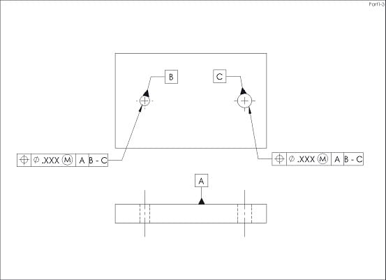
Referencing a multiple datum feature B(M) - C(M) is generally a legitimate practice, as long as long as the virtual condition boundaries are well defined. How this would play out in the context of the quasi self-referencing FCF in your example is actually an interesting question.

The TGC's (simulators) for datum features B and C would be pins, fixed at the VC sizes of B and C. These would be the same size pins as would be needed for gaging the position tolerance itself. So the A|B(M)-C(M) references would apply the same control to the features as A| only in this case. I suppose this means that specifying A|B(M)-C(M) is legitimate, but redundant.

3DDave,

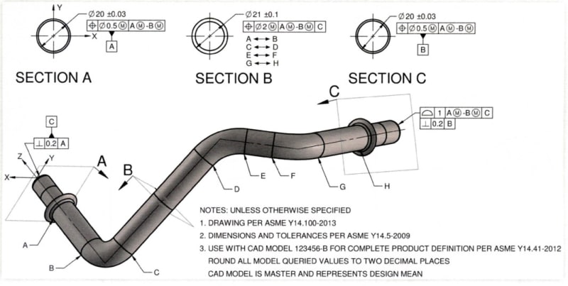
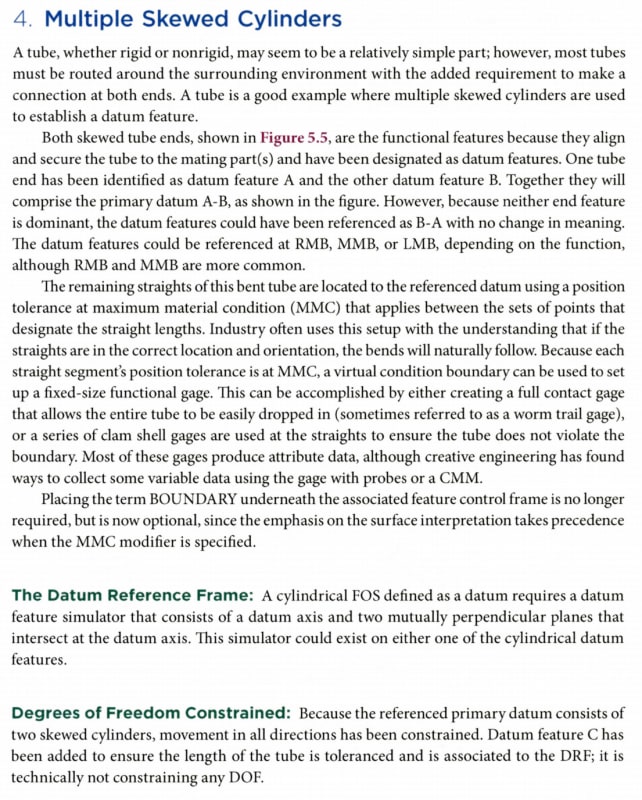
The bent tube examples highlight certain issues, some of which expose limitations in Y14.5's current theory.

The way I think of it is that we can always define the TGC's / simulators and identify the degree of freedom constraint from those. Y14.5 describes the requirements of TGC's near the beginning of the DRF section (7.5.2 in Y14.5-2018), and I would say that these requirements are generally correct and not controversial. The TGC's have perfect form, basic orientation and location relative to the other TGC's, are fixed in size for MMB or LMB and adjustable in size for RMB. This tells us what we need to know to define the gage elements needed to hold the part. From those gage elements, we can identify which degrees of freedom would be constrained and which would be left open. This type of analysis works well, even for the bent tube examples with A-B datum features that are skewed relative to each other (or two offset parallel planes). The TGC's (and gage elements) are still basically oriented and located relative to each other. The A-B TGC's in the OP example would constrain all 6 degrees of freedom, but not overconstrain.

If we try to go further and identify datums and a DRF, this is where things can go off the rails. Y14.5's datum theory is based on simple configurations of datum features, and does not generally perform well when applied to less simple configurations. This is why we struggle to define a single datum axis from the two skewed cylinders - there is no unique way to do this. We have two TGC's that are skewed relative to each other, and there is not a unique or obvious way to define a three-plane coordinate system in them. If we look at the Primary Datum Features table near the beginning of Y14.5's DRF section, we see that the 2 skewed cylinders form a Complex datum feature and the datum is an Axis, Point, and Center Plane. To me, this description is only useful for special-case features like the oblong cone shown in the table.

As you mentioned, another issue that the bent tube examples introduce is part flexibility. For many parts of this type, there is enough flex to bend the part into full contact with multiple TGC's that would otherwise overconstrain a fully rigid part. It appears that this type of consideration may have been used in the SAE excerpt that was posted.

Evan Janeshewski

Axymetrix Quality Engineering Inc.
 
Status
Not open for further replies.
Back
Top