Continue to Site

Eng-Tips is the largest engineering community on the Internet

Intelligent Work Forums for Engineering Professionals

  • Congratulations KootK on being selected by the Eng-Tips community for having the most helpful posts in the forums last week. Way to Go!

Dome/3d Shells Reinforcement 2

Status
Not open for further replies.

RamiHabchi93

Civil/Environmental
Jan 22, 2017
26
hi,
According to ACI 19.4.9 provision "Reinforcement Required to resist shell bending moments shall be proportioned with due regard to the simultaneous action of membrane axial forces at the same location."
Does this mean that I should treat each portion of the shell's section as a column subject to axial and bending simultaneously?
It seems impossible to do it with the varied combinations of moment and axial force which makes it difficult to find the critical section.So how we do it? and thank you
 
Replies continue below

Recommended for you

Does this mean that I should treat each portion of the shell's section as a column subject to axial and bending simultaneously?
It seems impossible to do it with the varied combinations of moment and axial force which makes it difficult to find the critical section.So how we do it?

Essentially you wind up figuring the steel required for moment and checking the interaction with axial load. The last time I did one of these, the tensile forces controlled over compression. If you are worried about overall buckling: there are a variety of formulas out there for that. Most of time, buckling is not a issue. (Displacement will be one first. Assuming we are talking about point loads here.)

And keep something in mind for any buckling formula you find: it needs to be modified to account for initial imperfections.
 
WARose thank you
By saying:checking the interaction with axial load, you mean checking the compressive stress if < compressive strength f'c?
And for shear and bending moment design did you divide shell's section into portions and design each portion under it's corresponding loads?
 
The sandwich model for shell elements from the FIB Model Code is one way of dealing with this situation. Handles all stress resultants from an analysis including in/out-of plane shear and twisting moments (if you have them; might not if using hand methods).
 
Thank you for the reply
Steveh49 I have read FIB.in torsion verification what does dk means?I cant find its definition.
And for in plane shear do I use shear resistance of 7.3-8 or shear transfer of 7.3-33.In aci for shells in plane shear reinforcement is done for shear friction transfer.
 
The sandwich model is in section 7.3.2.2 of Model Code 2010, but it doesn't give the detailed explanation that I thought it did (there's a step missing that's a bit hard to work out just from the Model Code). I was actually thinking of FIB Bulletin 45 "Practitioners' Guide to Finite Element Modelling of Reinforced Concrete Structures" sections 2.3.5 to 2.3.8 which include a worked example.

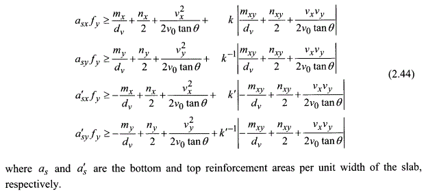
The sandwich model gives a method of resolving the eight stresses that a finite element shell analysis gives as results into numbers that can be used for design of reinforcement and checking of the concrete strength. After applying the sandwich model, you get four in-plane forces for reinforcement design (top x-direction; top y-direction; bottom x-direction; bottom y-direction) as well as the principal out-of-plane shear force. You can then use your own concrete code's provisions (eg ACI) to design the reinforcement/check shear/check concrete compressive strength.

In-plane shear is rolled into the equations of the sandwich model so you won't design for it directly. It appears in the equation for reinforcement area in all four layers.

Torsion 'dk' is the diameter of the circle that might be inscribed at the most narrow part of the cross-section (Model Code 2010 Figure 7.3-18). You don't need the torsion rules for shell/sandwich model design and I've never come across 'dk' before to be honest.


Thank you for your reply.
How do you design shell for torsion?In the sandwich model nxy=nxy/2+Mxy/dv
But the problem is that if we take the whole cross section of a shell in addition to the moments mxy on the section the out of plane shear create an additional torsion moment about the center of the section.so how do I take that into account?designing for nxy given is not enough.
And could I use nxy in another code (aci)?thank you
 
I'm assuming you're trying to design for the output from a finite element analysis. I'd prefer one set of numbers per element (ie averaged) and this is usually adequate for design (provided the mesh was fine enough for analysis). It wouldn't matter though if you had four sets of numbers per element, just more post-processing.

I'd take the numbers output from the FE analysis (Nx, Ny, Nxy, Mx, My, Mxy, Vx, Vy) and feed them directly into the sandwich model equations (image below) without modification. By doing this, the eight stress outputs listed above are converted to four equivalent/effective in-plane forces to be resisted by the reinforcement (top x-direction; top y-direction; bottom x-direction; bottom y-direction). These effective in-plane forces include the effects of in-plane shear Nxy and twisting moment Mxy. There is no need for torsion rules to be used: you just apply reinforcement area multiplied by design reinforcement strength.

You then check out-of-plane shear and concrete compression strength separately. The concrete compression strength check accounts for the components of shear forces that can't be resisted by the reinforcement.

FIBsandwich_qzwh68.gif
 
Status
Not open for further replies.

Part and Inventory Search

Sponsor