Continue to Site

Eng-Tips is the largest engineering community on the Internet

Intelligent Work Forums for Engineering Professionals

  • Congratulations cowski on being selected by the Eng-Tips community for having the most helpful posts in the forums last week. Way to Go!

double wood beam - shear control? 4

Status
Not open for further replies.

mats12

Geotechnical
Dec 17, 2016
181
Hi, maybe that is a silly question but its not my area...

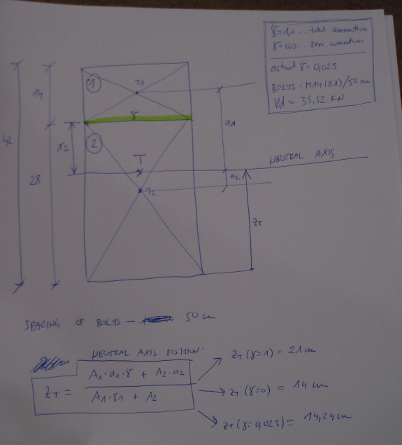
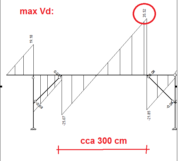
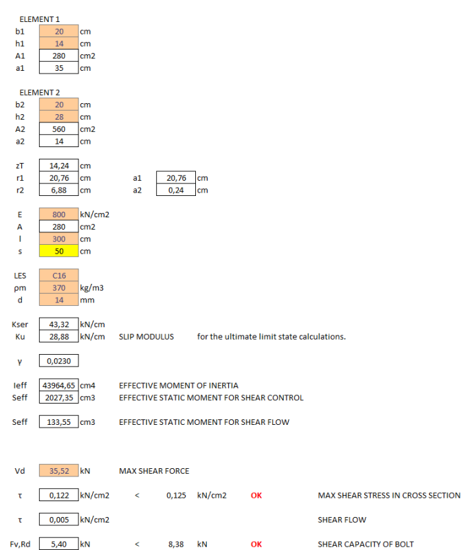
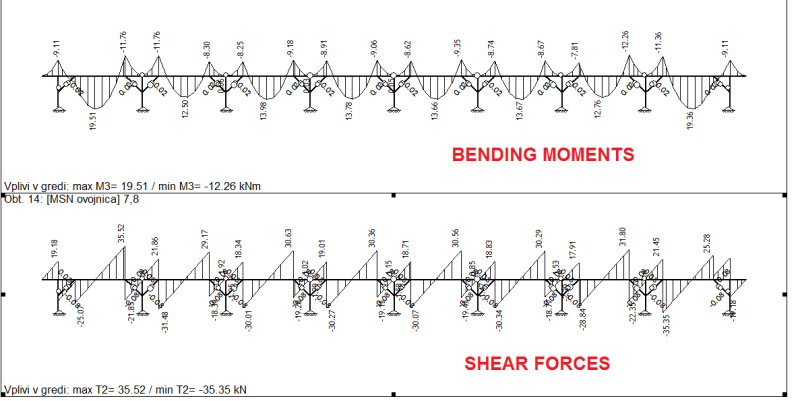
Lets say we have a roof wood beam (element 1), but its not sufficient on its own (shear forces too big) so we add another wood beam (same material) on top of it (element 2).

Can I consider this now as one element when making control for shear forces? Does there have to be connection?

I know it has to be connected when dealing with bending (shear flow between elements so we need bolts or other connectors) but what if I know that element 1 is Ok as far as bending goes on its own? Because of that i really want to avoid calculating shear flow and bolts and calculating effective moment of inertia Ieff - because of a slipping between elements, etc.(according to eurocode 5).


les_r0isb6.png


BTW i have to connect elements somehow so bolts should be OK?

22222222_umgaaa.png
 
Replies continue below

Recommended for you

Mats12:
It never ceases to amaze me how you OP’ers. dribble out important structural info. during the first 19 or 20 posts (responders guessing at what you are really doing), while we try to drag the info. out of you. Maybe your ‘Agreement about double wood beam and bolts only,’ should have included the ‘silly’ proviso that it, and the who structure work, actually work structurally; a small detail that the contractor might miss in asking you to save his a$$. You might also consider involving a local Structural Engineer, if this is ‘not your area.’ What happens in the other elevation or in plan, is still an important structural consideration, and is also still a mystery.

I would start with well seasoned timbers (kiln dried) to minimize shrinkage. I would use some of the newer structural screws, one brand or another, instead of through bolts and structural glue in the joint to minimize the joint slippage and max. the shear transfer. You could put a couple split rings in the joints at each end of each beam to improve shear transfer and composite action. You might wish that you didn’t have hinges at the joist/beam bearing plane, and at the beam/column bearing elevation, and you should do something about this. Given what we’ve heard so far, your many 45̊ kickers will probably be very difficult to do well with wood. You might consider pre-fabed steel kickers that through bolt at the column and screw up into the beam. These would be 24-36" long, 6" wide by .25" thk., with a welded 2x2 HSS diags., black wrought iron in appearance. These can be made with some degree of precision and the connections can be made with some degree of confidence. Note also, that with the use of the kickers, you have to hold the beam ends down to the top of the columns for things to work properly. Thus, I would add some “T” straps btwn. the two beams and each column; this holds the beams together lengthwise and holds them down on the column. Finally, I would put the added beam member on the underside of the larger beam member, and make it only 5m, less a full column width long, to fit btwn. the columns. It would bear on the kickers, which are pressed up tightly to its underside before they are attached to the column by through bolting. I would set the beams on a 1/16" shim atop the column (some engineering judgement and thought is needed here). Once the kickers are attached, I’d pull the shims, press the upper beam down onto the column and fix the “T” straps in place.

While this may seem a little fussy, remember, you are working to save the contractor’s ‘bull,’ and he should now make an effort to make the whole thing work right now.
 
The difficulty is going to be getting enough capacity on the bolts to resist the horizontal shear. I don't believe it can be done even with 4" dia. shear plates and 7/8" dia. bolts at minimum spacing.

It appears to me that the contractor may have to accept a compromise.

BA
 
BA:
I haven’t run any numbers, as you were so kind to do for us, for lack of OP’er. basic structural info., so I’m not absolutely sure how it would shake out either. I was not intending that the end shear pls. would take all of the horiz. shear. They would just take the higher shear flow at the ends, where the alternative would be 10-12? structural screws in 16-24". They would also provide some protection against the horiz. shear/notch affect/reentrant notch at the end bearings. I would still space struct. screws over the length of the beams to take most of the horiz. shear in a more distributed fashion along the beam, and to clamp the two parts together. I suspect the struct. glue/adhesive would do the trick over the middle half of the beam, as long as it is protected from environmental conditions, and the codes would allow us to start using struct. adhesives. I like the struct. screws from below because they are protected from water standing atop the beam. We don’t know what the roof protection is, do we? My intention for the 1/16" shim atop the column, then its removal and pressing the beam down, is to really seat the lower beam bearing on the horiz. leg of the kicker to assure some distrib. of the vert. reactions, btwn. the kicker and the column top.
 
i made some calcualtion based on eurocode 5.

if this is right, it means that bolts dont contribute much!
gama = 1,0 means complete 100% connection between elements
gama = 0,0 means there is no connection

for bolts M14 (8.8) at 50 cm spacing I got gama = 0,023 which is almost zero, but enough for controls to be OK...

Bolts alone are pretty ineffective because they dont produce enough resistance for shear flow development... if i choose smaller spacings its still pretty ineffective.

B1_tmnbnw.png


B2_p4tww1.png


B3_xyqxji.png
 
mats12,

You started out with 5 m simply supported beams. Your shear force diagram seems to be taking into account some form of continuity, but it is not clear which spans are loaded and which are not. In order to analyze the structure, you would need to know the stiffness of the columns. I don't believe your shear diagram is accurate.

It might be prudent to retain a structural engineer to analyze the structure properly and to make recommendations to the contractor.


BA
 
dhengr,
I haven't used structural screws to any extent but would have to penetrate 140 mm (5.5") before becoming effective so the screws would probably by nearly 12" long. Would that be efficient? Would lag screws be more economical?

I like the idea of using structural adhesive, but I'm not sure it would be effective in an exterior exposure. My knowledge of adhesives is not current.

As for the kickers, I don't think they help much in the case of gravity loads, particularly if there is pattern loading but that would have to be analyzed.

BA
 
Given all the information presented so far, I feel that the non composite stacked solution is a clever and appropriate solution. Install vertical bolts with washer plates designed not for horizontal shear but, rather, to ensure the distribution of vertical shear between plies. This should be doable and would take care of the issue that I mentioned above.

I like to debate structural engineering theory -- a lot. If I challenge you on something, know that I'm doing so because I respect your opinion enough to either change it or adopt it.
 
I'd be inclined to halve the new timber the hard way, and glue the halves to top and bottom of the extant timber.

I've had good results with Gorilla Glue; is that approved anywhere?

Secure the top and bottom caps with a crapload of screws while the glue cures; that way the screws 'only' need a grip length of 7cm.


Mike Halloran
Pembroke Pines, FL, USA
 
I guess vertical bolts still have the shrinkage problem no matter what use they're put to. Pesky shrinkage.

I like to debate structural engineering theory -- a lot. If I challenge you on something, know that I'm doing so because I respect your opinion enough to either change it or adopt it.
 
There is a shear force diagram and bending moment diagram for the whole thing for those who are confused by picture posted above:

FOR_zalbzb.png
 
Timber grade C16 is really bad. How did you come up with it?
 
I didnt!
They say thats the timber grade they have - investor has his own woods so he prepered own beams.
Usually I choose C24.
 
mats12,
Your bending moment and shear diagrams are wrong. It appears to me that you have entered the wrong support conditions into your program.

BA
 
BAretired - I dont understand. What is wrong!? I think diagrams are pretty expected? Please elaborate!
I used pinned supports for timber columns (vertical and horizontal support + free rotation)
 
Based on the moment diagram, I'm seeing a beam splice at each post and posts that don't introduce much rotational stiffness (end span diagrams).

I like to debate structural engineering theory -- a lot. If I challenge you on something, know that I'm doing so because I respect your opinion enough to either change it or adopt it.
 
You appear to be treating the upper ends of the knee braces as hinged supports. They are hinged, but they are not hinged supports, i.e. the hinge can move vertically. When it does, it causes compression in the knee brace and moment in the column. With your shear diagram, the moment in the end columns would be very large.

What load are you assuming in your design? Are you considering the possibility of unbalanced live (snow) load?

BA
 
I think my supports are OK. In previous picture I show forces for beams ONLY.

Here are diagrams for all forces including columns. Also deflection diagram.

I think my model is alright. And yes, snow is considered.

DEG1_czsuku.png
 
I apologize. You appear to have considered the knee braces correctly in your analysis. The end columns have a moment of 10 or 11 kN-m which will require a fairly stocky section.

BA
 
Hello, this is my first post here. If you want to add an additional beam on the top, I'd do that but instead of installing bolts vertically I would install them on an angle, see attached sketch.. I think that would take the shear stresses.. I am not much experienced so it's just a suggestion.


 http://files.engineering.com/getfile.aspx?folder=9f500803-7411-46d6-a4be-eaae94ab3684&file=IMG_1934.JPG
Status
Not open for further replies.

Part and Inventory Search

Sponsor