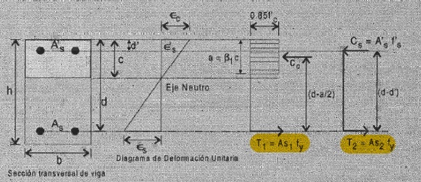
Basically, ACI assumption about the location of neutral Axis of a moment subjected member begins directly matching Tension of steel with compression of concrete and compression steel. Developing this idea a proportion is calculated on how much is equilibrated by concrete and the rest then resisted by steel.
when improved, the concrete portion occupied by steel is discounted.
Then through Navier hypothesis the deformation of steel is calculated and so the stresses. Also the neutral axis location.
Done the above, nominal moment is computed by assuming a coupled behaviour of forces. sum(Forces*distances)
My doubt is about the first equilibrium assumption and why moment is computed that way.
---------------
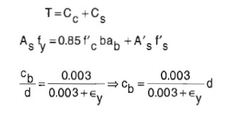
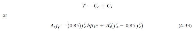
The external and internal forces equilibrium of a member's section responds to:
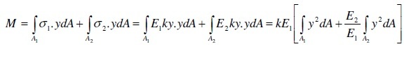
E1, E2, respective Young's modulus, k: Navier slope
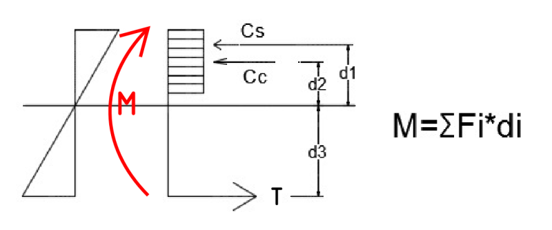
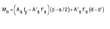
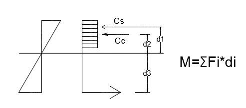
And the moment developed by the forces that resist it should be measured by sum(F*di) (As expressed above), not with (d-a/2) and (d-d') distances:
 (autocad picture)
The way it's done in ACI, when multiplying forces by distance (d-a/2) and (d-d'), correspond to forces rotating at the midpoints of each one of those lines.
-----
Another way i have seen this can be done,
before cracks:
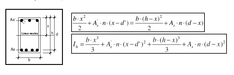
After cracks:
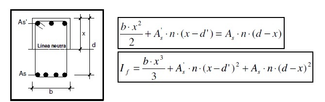
The problem of this last method is that the moment is spread only through the areas (and distances) without taking into account that the compression steel doesn't need to be as loaded as tension one,
-------------
I don't see the need of directly match Ts=Cc+Cs, becauses their proportions respond also to distance to neutral axes. I think it should be T*d3=Cc*d2+Cs*d1 (following the autocad picture).
It is similar to the way moments are computed in interaction diagrams, but in that case distances are computed to the gravity center of cross sections when it is symmetrical
Why is ACI not taking distances to neutral axis?
when improved, the concrete portion occupied by steel is discounted.
Then through Navier hypothesis the deformation of steel is calculated and so the stresses. Also the neutral axis location.
Done the above, nominal moment is computed by assuming a coupled behaviour of forces. sum(Forces*distances)
My doubt is about the first equilibrium assumption and why moment is computed that way.
---------------
The external and internal forces equilibrium of a member's section responds to:
E1, E2, respective Young's modulus, k: Navier slope
And the moment developed by the forces that resist it should be measured by sum(F*di) (As expressed above), not with (d-a/2) and (d-d') distances:
The way it's done in ACI, when multiplying forces by distance (d-a/2) and (d-d'), correspond to forces rotating at the midpoints of each one of those lines.
-----
Another way i have seen this can be done,
before cracks:
After cracks:
The problem of this last method is that the moment is spread only through the areas (and distances) without taking into account that the compression steel doesn't need to be as loaded as tension one,
-------------
I don't see the need of directly match Ts=Cc+Cs, becauses their proportions respond also to distance to neutral axes. I think it should be T*d3=Cc*d2+Cs*d1 (following the autocad picture).
It is similar to the way moments are computed in interaction diagrams, but in that case distances are computed to the gravity center of cross sections when it is symmetrical
Why is ACI not taking distances to neutral axis?