Continue to Site

Eng-Tips is the largest engineering community on the Internet

Intelligent Work Forums for Engineering Professionals

  • Congratulations SSS148 on being selected by the Eng-Tips community for having the most helpful posts in the forums last week. Way to Go!

Dovetail groove GTOL 5

Status
Not open for further replies.

dthom0425

Mechanical
Dec 6, 2018
47
Hi all,

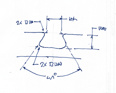
I have a plate that has a dovetail groove cut into it for a gasket. Link below to a somewhat similar dovetail groove to get my point across.

Link

Keep in mind this dovetail groove is a tool path around the entire perimeter of the plate and not just a local feature.

So my issue is that, someone gave the major diameter of the dovetail a positional tolerance and made it a datum feature. Also, they controlled the neck diameter of the groove with a positional tolerance back to the datum feature established by the major diameter of the dovetail.

I feel like this isn't correct. Would you all agree? The dovetail groove is not a true feature of size (locally it is) since it routes around the entire perimeter of the part.

I guess I was thinking a profile tolerance could take care of the entire grove back to the main datum reference frame. Or maybe even a profile tolerance with additional MMC positional tolerance (like Fig 8-24 Y14.5-2009)..but that may be overkill.

Any suggestions?

Thank you

 
Replies continue below

Recommended for you

By "major diameter" you mean the distance between the bottom radii of the groove (produced by the major diameter of the milling cutter), correct?
 
dthom0425,

Its certainly possible to utilize directly toleranced dimensions attached to either the dovetail itself or gauge balls/cylinders to define a dovetail. Attaching a position tolerance to the "neck" or "major diameter" as you call them - I assume these are both dimensions tangent to either the radii at the top/bottom of the groove or the sharp edges if no radii are present - are troublesome as these are not stable features from which one can establish a repeatable UAME. Also if its what I'm thinking the "major diameter" exists inside the material - not impossible but it makes it harder to verify, it would be more common to use gauge balls/cylinders for this dimension instead. MMC position might provide a workaround to utilizing position though.

That said, there are ways to dimension a dovetail unambiguously with profile. See the attached, it can be modified with composite/multiple single segment if desired for refinement.
 
 https://files.engineering.com/getfile.aspx?folder=872f0eb5-28c3-4394-a105-3641f17708cb&file=Dovetail_Dimensioning_Guide.pdf
dthom0425,

From a dimensioning and tolerancing point of view, that is a nasty shape. Your drawing is for the cutter. This is not how you would dimension the slot in your drawing of the plate. Do not specify tools. Your tool could make two passes to get the correct slot width.

GDTslot_smsim5.png

This is a better way to describe your slot, especially if you are applying GD&T controls. I am assuming that you are using the flat faces, not the radii.

--
JHG
 
@DThom0425
is it possible to provide a drawing?
I believe as described is not possible. because of the geometry the tool must have an entrance and an exit.
quote "Keep in mind this dovetail groove is a tool path around the entire perimeter of the plate and not just a local feature." un quote[highlight #EF2929][/highlight]
if I have mis interpret the info apologies in advance.
 
mfgenggear,

Yes it is possible, if the tool is smaller than the slot and it makes two passes. This is all the more reason to not specify tools.

--
JHG
 
@Drawoh

yes agreed, the tool required would have pass through of the slot.
but must maintain the required under cut.
yes a one pass would not be possible. which is usually desired.
 
mfgenggear, drawoh,
Milling of a slot of this shape even when it's passing through, requires roughing with a regular endmill before the less rigid form tool machines the undercut.
 
@chez311
very well done I was thinking it but didn't comment on it because not knowing if it was permitted.

a question for all of you @Chez311 ,@drawoh,& Burunduk & the OP
why not use a straight slot for an O-ring ?
why a dove tail, which is usually for a machine guide.
 
So that the O-ring has less tendency to be pulled out of its gland.
 
mfgenggear,

A dovetail helps hold an o-ring in place during assembly (or shipping possibly) while allowing sufficient space for compression of the o-ring. A straight groove of the size that would be needed to hold it in place firmly would have too small of a cross-sectional area and would extrude or possibly split the o-ring - most straight o-ring grooves of the proper size (ie: cross sectional area of the groove is sufficiently greater than the o-ring cross section) are loose fits.
 
yes but automotive applications use a slot, even on shafts rotating high RPM applications.
it should be stable if it is assembled with a mating part. something for the OP to consider.
but if has to manufacture a dove tail it is what it is.
 
mfgenggear, drawoh,
Milling of a slot of this shape even when it's passing through, requires roughing with a regular endmill before the less rigid form tool machines the undercut.

@Burunduk
good point, it would minimum of three passes, cost of mfg just increased.
 
Burunduk said:
mfgenggear, drawoh,
Milling of a slot of this shape even when it's passing through, requires roughing with a regular endmill before the less rigid form tool machines the undercut.

I did not know that. This is all the more reason to not tell the machinist how to do his job.

--
JHG
 
@ Drawoh
I gave you a star, be cause let the guys on the floor figure it out but it does not hurt to have a fundamental of basic machining for
designing and tolerancing. I believe this has been good discussion beyond just dimensioning the dove tail.
 
The main characteristics to be controlled for o-ring grooves are local section area, to create the correct amount of pressure and local depth to provide the correct amount of deformation, and not having random shapes like saw-tooth surfaces that the o-ring cannot occupy, even if the area is OK.

I can see no benefit to a position tolerance on the groove width at any depth; there needs to be control of the profile on the unpressurized side of the groove to prevent the o-ring escaping the mating part, and some use for controlling the entire perimeter to keep from annoying the installers. No one likes it when the o-ring is too tight or forces itself out of the groove from being too long.

However, you can specify the use of datum features and datum references over short distances, like per-millimeter, if there is a need.

I had occasion to do this where using the entire face of a part as a datum feature was not going to work - a 40 foot long piece of steel angle with about 3 feet of curvature due to welding on one side; the details added to it only needed to interface with foot long sections, so I referenced just that length relative to the details. It all got straightened with bolts at assembly, but QC had no way to restrain it for inspection on the shop floor.

Frankly, it's a thankless job. You can involve FEA to analyze the sensitivity to contact pressure for every possible variation in the section and durometer of o-ring and analyze it to death or just accept that the form tool will produce an acceptable part based on checking just the groove depth.
 
OP said gasket.
Perhaps he'll come back to talk about it.

I'm guessing it is fairly likely we are talking a face-sealing o-ring.

Typical feature details and tolerances for o-ring grooves to let the o-ring seal properly in my experience are:
- surface finish on the "bottom" of the groove (and on the mating part's "counterface")
- the depth of the groove to compress the o-ring some minimum % of cross section diameter. Like 15-30% based on service.
- as others said, MINIMUM groove volume so the squished or-ing can expand unrestricted when the cover is tightened.
- Whichever face of the groove will restrain the o-ring under max pressure needs to be smooth. For serious pressure applications the tool pass thru notch would need to be on the groove "ID."

Sizing the "length" of the groove (and of course the o-ring) so the o-ring has to be stretched a little bit will generally hold the greased oring in place even with a groove traced around the face of a non circular / rectangular cover plate. The parker catalog talks about how much stretch is OK before the grooe depth has to be made a bit shallower. I'm thinking 3% stretch is no big deal. In some applications dovetailing the groove "ID" (circular or rectangular/oblong covers) will let a stretched o-ring really hang on, so going crazy with a tight dovetail entrance is not necessary. I'd spend some time thinking about whether a tight mouthed dovetail leaves enough expansion for o-ring compression. There is probably some critical minimum angle on the dovetail, perhaps related to o-ring cross section.
As such, the groove ID needs to be held within 3% or so, so I figure the lengths of the sides and radiuses are what count for o-ring retention.


Status
Not open for further replies.

Part and Inventory Search

Sponsor