Continue to Site

Eng-Tips is the largest engineering community on the Internet

Intelligent Work Forums for Engineering Professionals

  • Congratulations KootK on being selected by the Eng-Tips community for having the most helpful posts in the forums last week. Way to Go!

Drafting missing lines from 3D

Status
Not open for further replies.

dihen

Mechanical
May 28, 2013
19
Hi guys, I never thought I would, but I'm struggling with the drafting mode...
I want to create some view containing 3d letters, but every time I lost some details...
See the video:

-Interfering Solids is activated (both checkbox)
-The only thing that has effect on the lines is the tolerance... but not the same value pro view...
On the front view I got better result if I set to tolerance low value.
On the right view (same letter although) I must play with values to find the best result...

Is there something magic way to get a good result immediately? I have more hundred drawings I don t have mood to play this game for every view .... :(
 
Replies continue below

Recommended for you

Yes there is a magic trick ! :)
But, when looking at the drawing, Press Ctrl+Shift+Z ( this will start a very old Zoom dialog)
In the top right on that menu enter 1 and press Enter.
This will , on your screen, display the drawing in the same scale as when printed on paper. 1:1 ( You can compare some known size with a wooden ruler that you place on the screen.)
If you cannot see the error now, you will not see it printed either, and if you don't , -don't bother.
I have so many times discussed with users who had zoomed heavily on the screen and where worried over similar errors and in the end that drawing was exported to pdf, where the line-width also scales and that error , on the paper, became a . dot.

The magic trick :
Zoom that view such to a suitable size on your screen ( this trick is depending on the zoom factor.) then edit the view -settings, set that view tolerance to 0 and apply.
NX will then , since 0 is impossible, find a suitable tolerance value and 99.9% the error you saw is gone. If not , try zoom slightly more and try another 0.


Regards,
Tomas
 
I too think your screen settings and video driver could be the big factor on how your lines look to you.
This issue was more common in "the good old days".

Jerry J.
UGV5-NX1961
 
"The magic trick :
Zoom that view such to a suitable size on your screen ( this trick is depending on the zoom factor.) then edit the view -settings, set that view tolerance to 0 and apply.
NX will then , since 0 is impossible, find a suitable tolerance value and 99.9% the error you saw is gone. If not , try zoom slightly more and try another 0."

Zoom: Done. (Simply zoom with scroll?)
Set the tolerance to 0: Done
Nx set it automatically something very tiny value: done.
Is the error gone? Unfortunately, not:( (it is actually worse than before.)

beetween 0.001 and 0.01 the result is ok... but all other value deletes more and more lines.
So in this case: the lower the value, the worse the result.

We convert the drawings to dxf and some other colleagues work with them in autocad, So they won't really be printed out.
 
I am puzzled why this did not work , it should.
Does this model contain intersecting solids ?
What font is used to produce these letters ? ( fonts are quite often not watertight outlines and also often defined by splines.)
Will it make a difference if you Right click - "Update display" when you look at these views ? -What you see on the screen is not exactly the same as what you print.
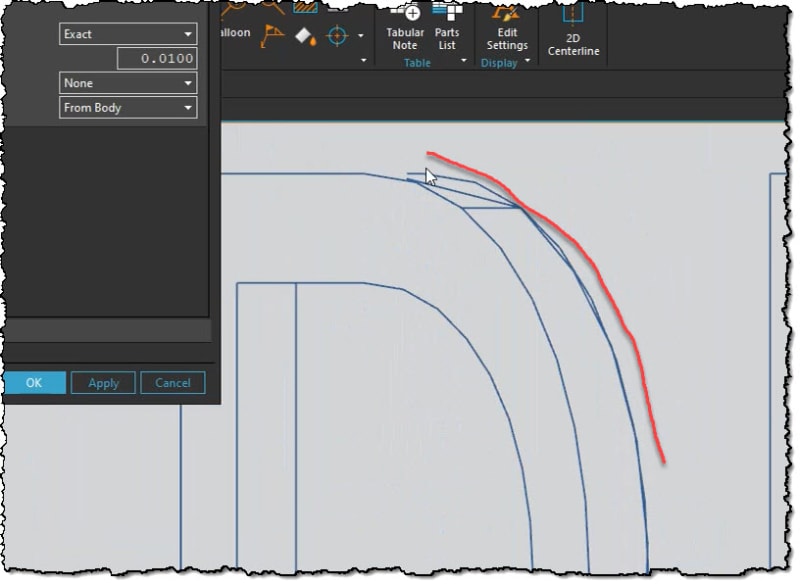
The chord-lines seen in the images below is an effect of the graphics adapter faceting and will not be printed.
2022-04-08_16-29-49_n948hf.jpg

How do Autocad use this data ? as drawings or 3D ? Will it be noticed in Autocad ?

Regards,
Tomas
 
Hi again :) ,
I run an examine geometry (See the video)
And I also recorded the "zoom and set the tolerance to zero" trick.
For the front view it works, on the right view it does not.
It is so for all 3d text, independend whether it is "SolidBody" (without fonts) or sketch driven extrude feature. (with fonts)
I always had to playing with the values to get the best result :(
 
 https://files.engineering.com/getfile.aspx?folder=6c42a215-bb69-4cd0-a81a-23416fad6de0&file=Examine_Geom.mp4
Does this error matter ?
Is it visible when plotted ? If not , why bother ? ( the zoom scale = 1 replicates "as plotted" scale on your screen, nothing more than that.)
You say convert to Autocad, via DXF/DWG ? Does that produce anything usable at all ?

These characters, are these created in NX or in some other software ?
Why are they non-parametric ? - Imported ?
It could be that these , if imported, are defined by surface types that is the reason for this.
you could try , in the file where these reside, run the "Optimize Face". That command cleans and simplifies solids/surfaces from things not visible to the human eye.


Regards,
Tomas
 
Status
Not open for further replies.

Part and Inventory Search

Sponsor