There's a project in my office that is in a low seismic area and is using conventional structural steel with composite slab on metal deck and ordinary braced frames. I was helping size base plates and bearing plates during some last minute detailing before the project went out the door and noticed all of the slabs on metal deck have #5 drag bars wherever there is a braced frame. Would someone be able to explain the reasoning for this? I am assuming the drag bars are being used to enhance the transfer of forces from the diaphragm (concrete on metal deck) to the braced frames but I have never learned about this method in school and would like to understand the reasoning behind it.
Navigation
Install the app
How to install the app on iOS
Follow along with the video below to see how to install our site as a web app on your home screen.
Note: This feature may not be available in some browsers.
More options
Style variation
-
Congratulations cowski on being selected by the Eng-Tips community for having the most helpful posts in the forums last week. Way to Go!
You are using an out of date browser. It may not display this or other websites correctly.
You should upgrade or use an alternative browser.
You should upgrade or use an alternative browser.
Drag Bars at Slab on Metal Deck 1
- Thread starter TylerM94
- Start date
- Status
- Not open for further replies.
- Thread starter
- #3
The framing plan is conventional infill beams range from W12x40s to W16x50s. Girders are typically W21s or W24s. The slab on metal deck is reinforced with welded wire fabric. I am still confused as to the reason for the "drag bars" but since they appear on level 2-5 they must be serving a purpose... Just not sure what exactlyr13 said:BTW, what is the framing plan and reinforcing pattern in the composite slab? Also, what explanation was given by the designator?
I believe the designer think there is thrust along the braced frame, and that WWF alone is inadequate to address it. I don't agree with it, but not against it either, as it is a prudent measure. I would just call out the bar size and length, and spacing, if multiple.
-
1
- #5
OP said:...I have never learned about this method in school...
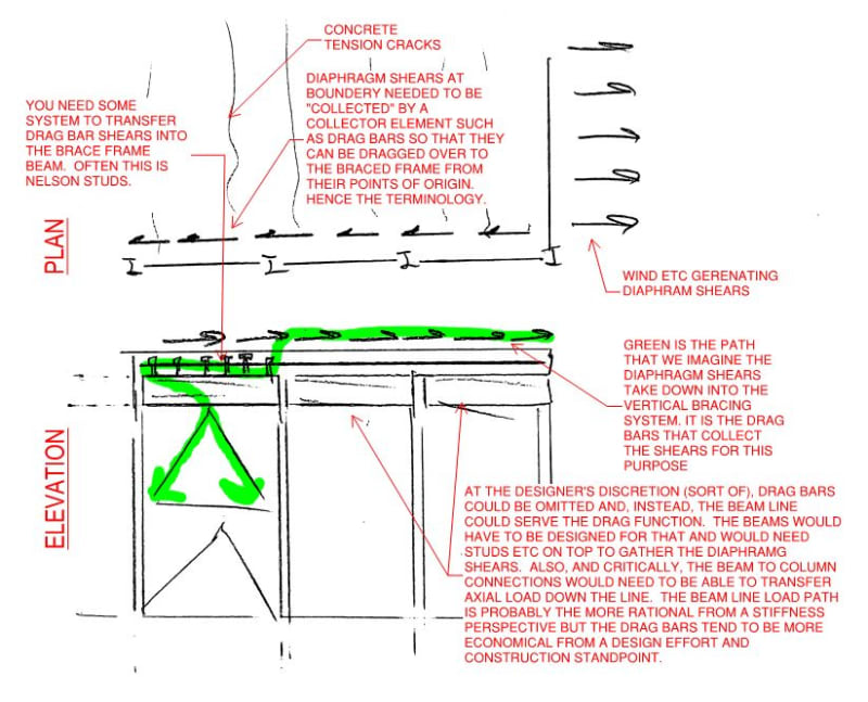
Ditto. I've attempted to explain the fundamentals below. The whole thing tends to be non-obvious because there are multiple ways that designers can choose to tell the story of how diaphragm shears get moved around. It's kind of a choose your own adventure thing.
You may also find value in this free resource: NEHRP Steel Deck Diaphragm Guide. It focused on seismic but all the the fundamental aspects of load transfer will apply to non-seismic situations.

- Thread starter
- #6
Yep, what Koot said. Typically we do this with field welded shear tabs or other huge bolted monstrosities at the beam/column connections. Recently I used added bars in the deck instead of dumping axial through the beam/column connections, like OP is talking about, along the frame line because I had SidePlate frames orthogonal to my braced frame lines. Apparently a 700kip drag force through a SidePlate kills the SidePlate 
R13 what do you mean thrust along the frame?
R13 what do you mean thrust along the frame?
dold said:Recently I used added bars in the deck instead of dumping axial through the beam/column connections,...
r13 said:I believe the designer think there is thrust along the braced frame, and that WWF alone is inadequate to address it. I don't agree with it,...
Any difference of the above mentioned actions?
@r13: your use of the word "thrust" threw me off the scent a bit. It's not wrong but it's also not commonly used in this situation in the space that is North American building structural design. Rightly or wrongly, in my mind thrust conjures up an inclined compression force requiring lateral restraint.
dold said:Apparently a 700kip drag force through a SidePlate kills the SidePlate
This touches on a point that I raised in my sketch. In my mind, the slab rebar:
1) Does a fine job of providing a belt and suspenders path for the load being considered.
2) Does a less convincing job of steering the axial load away from the beam line when it's not wanted there. That, particularly because the rebar is typically designed so as not to yield rather that to limit strain.
In your heart of hearts, how confident are you that the combination of your slab rebar and beam-column connection detailing actually does keep axial out of those side plates for both tension and compression? I'm sure that an appreciable amount of either probably voids the research that underpins that system, at least from the perspective of Sideplate's legal department.
Koot,
Point taken re: bar stiffness vs beam line stiffness. I had this internal discussion with myself. We used long slotted holes at these bypasses, but, admittedly, i did not calc out the bar elongation. Some solace to be found in the fact that you also have a whole football fields worth of steel deck that "isnt doing nothing"...if that makes sense. 20ga W3 deck is about 0.6in^2/ft of area in the strong axis, and it's pretty well bonded to the 'floor mass'. As W24x68 Ag=~20in^2. Say you have a 100ft wide floor plate (50ft 'drag trib' to each drag line), youd have 0.6in^2/ft * 50ft = 30in^2 of deck, (X)in^2 of rebar, 20in^2 for drag beam. Stiffness directly proportional to A*E. So...the deck takes most of the load? Even if we split the deck into 4 "quarter strips", each 25' wide. Then we have 15in^2 of deck (at E=29500ksi, mind you...cold work of forming) vs. 20" of drag beam (and deck edge angle/pour stop not)
not)
Furthermore, these forces are coming directly from the diaphragm itself (or...going in to the diaphragm, technically). So with the deck bonded to the 'mass' (concrete, floor covering, etc), how much of it do we want to consider? What's our load distribution looking like? FEM time? Waiiiitttt a minute...is this why semirigid diaphragm analysis always always just shows a huge shear hotspot at the brace, somewhat ignoring the drag beams (lateral members in RAM/RISA/ETC). It does seem to depend on the length of the drag. Is the deck that much stiffer than the drags/chords? And why have I not given this more than 30 seconds of thought before? I need to go play around with the membrane stiffness of semirigid decks some more and see what happens. I do typically modify those with some rules of thumb but this warrants further discussion.
Anyway, lets explore that rabbit hole. If it is in fact the deck that's doing all the work - do we even need drag beams? Assuming our hypothetical deck meets the shear demand at the frame beam. I've just gotten accustomed to running drag beams where youd normally see them. 9 times out of 10, the axial load doesnt even sweat the beam.
Similar to roof deck, can you count on composite deck (the steel deck itself) to form a 'quasi-continuous cross tie' like you can use strong axis roof deck for wall anchorage forces on a warehouse, etc? But you still have to have a chord. But if your drag force is higher than your chord force, whats the difference between drag force and chord force from the diaphragm's perspective? (only considering where drag force and chord force act in the same direction. Drag force due to quake_x, chord force due to quake_y)
R13,
I see what you mean about thrust. We're talking about the same thing. At first i thought you meant some sort of orthogonal forces.. Anyway, you said you dont agree that WWF might be inadequate to address this demand. Is this what you were getting at? I.e., the deck is capable of handling this? Clearly you were talking about WWF but what if youre using fiber reinforcing. I'm still not 100% on board with fiber.
Point taken re: bar stiffness vs beam line stiffness. I had this internal discussion with myself. We used long slotted holes at these bypasses, but, admittedly, i did not calc out the bar elongation. Some solace to be found in the fact that you also have a whole football fields worth of steel deck that "isnt doing nothing"...if that makes sense. 20ga W3 deck is about 0.6in^2/ft of area in the strong axis, and it's pretty well bonded to the 'floor mass'. As W24x68 Ag=~20in^2. Say you have a 100ft wide floor plate (50ft 'drag trib' to each drag line), youd have 0.6in^2/ft * 50ft = 30in^2 of deck, (X)in^2 of rebar, 20in^2 for drag beam. Stiffness directly proportional to A*E. So...the deck takes most of the load? Even if we split the deck into 4 "quarter strips", each 25' wide. Then we have 15in^2 of deck (at E=29500ksi, mind you...cold work of forming) vs. 20" of drag beam (and deck edge angle/pour stop
Furthermore, these forces are coming directly from the diaphragm itself (or...going in to the diaphragm, technically). So with the deck bonded to the 'mass' (concrete, floor covering, etc), how much of it do we want to consider? What's our load distribution looking like? FEM time? Waiiiitttt a minute...is this why semirigid diaphragm analysis always always just shows a huge shear hotspot at the brace, somewhat ignoring the drag beams (lateral members in RAM/RISA/ETC). It does seem to depend on the length of the drag. Is the deck that much stiffer than the drags/chords? And why have I not given this more than 30 seconds of thought before? I need to go play around with the membrane stiffness of semirigid decks some more and see what happens. I do typically modify those with some rules of thumb but this warrants further discussion.
Anyway, lets explore that rabbit hole. If it is in fact the deck that's doing all the work - do we even need drag beams? Assuming our hypothetical deck meets the shear demand at the frame beam. I've just gotten accustomed to running drag beams where youd normally see them. 9 times out of 10, the axial load doesnt even sweat the beam.
Similar to roof deck, can you count on composite deck (the steel deck itself) to form a 'quasi-continuous cross tie' like you can use strong axis roof deck for wall anchorage forces on a warehouse, etc? But you still have to have a chord. But if your drag force is higher than your chord force, whats the difference between drag force and chord force from the diaphragm's perspective? (only considering where drag force and chord force act in the same direction. Drag force due to quake_x, chord force due to quake_y)
R13,
I see what you mean about thrust. We're talking about the same thing. At first i thought you meant some sort of orthogonal forces.. Anyway, you said you dont agree that WWF might be inadequate to address this demand. Is this what you were getting at? I.e., the deck is capable of handling this? Clearly you were talking about WWF but what if youre using fiber reinforcing. I'm still not 100% on board with fiber.
dold said:Anyway, lets explore that rabbit hole.
Yes, lets. Fun. The key to much of my perspective comes from this assumption:
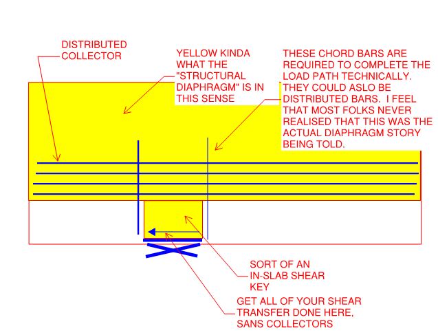
The concrete, the deck, and the beam all work together as a composite thing in real life and thus share the same strain at the beam line, at the level of the deck.
dold said:If it is in fact the deck that's doing all the work - do we even need drag beams?
I see a distinction between how it works for collectors and how it works for chords. In many cases, because of the assumption above, I feel that we probably do not truly require discrete chords as long as there some meaningful tension capacity in the deck in, say, the outer third of it. Somewhere I've got a paper on the use of "distributed chords" so it's not as though this is a thought that's never been thought before.
dold said:Some solace to be found in the fact that you also have a whole football fields worth of steel deck that "isnt doing nothing"...if that makes sense.
In the case of a collector, I feel this argument is muted by the fact that any axial stress located not direction over the beam line eventually has to travel laterally to the beam line. So yeah, there is stuff there but claiming a football field's worth might be a little aggressive.
dold said:We used long slotted holes at these bypasses, but, admittedly, i did not calc out the bar elongation.
An implication of my common strain assumption at the deck edge is that axial slip connections in the beams would not shield the beams from absorbing axial load. And that's assuming that slots actually function properly as slip connections which is pretty dubious. A properly functioning slip connection would really only shield the connection from absorbing axial load.
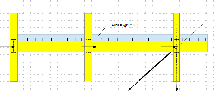
If there's one great job that I feel that rebar collectors do perform, it's this: they provide a belt and suspenders, backup load path around the connection should it be required. That's worth something in my book.
dold said:9 times out of 10, the axial load doesnt even sweat the beam.
That's not my experience but I suppose it depends how you come at it:
1) Making a beam-column of what used to be a beam kills your buckling capacity if there is not bottom flange bracing. That said, if you kicker brace your drag beams at close intervals by default, there will be little change.
2) The story that you tell about the axial load in the beams is sensitive to where you see the axial load being located vertically in space:
a) If you view the load as originating in the deck, then maybe the axial load is at the top of the beam and really little different from added strong axis flexure. Ergo no bottom flange bracing demand.
b) If you view the load as originating in the brace frame, then maybe the axial load is at the centroid of the beams. Ergo a classical incarnation of beam-column axial load.
dold said:is this why semirigid diaphragm analysis always always just shows a huge shear hotspot at the brace, somewhat ignoring the drag beams (lateral members in RAM/RISA/ETC).
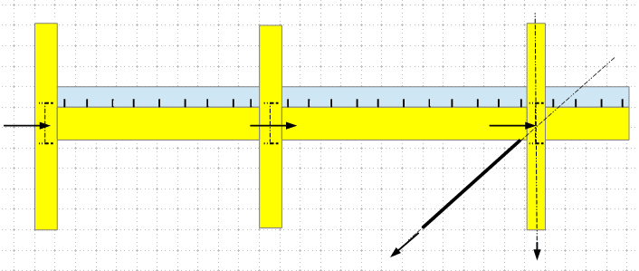
Yes. There was a time before we had explicit chords and collectors. Then, I believe that we were implicitly telling the story below which most practitioners reduced to simply: "just transfer all of the deck shear at the brace". In many regions, this is still the way of things.

Good post Kootk (@ 21 Nov 20 19:14 and the rest). I have to admit, I've not used drag bars typically. Following diaphragm theory, I've just checked the slab's shear capacity. (Acting as a beam.) One reference I have alludes to using this reinforcement when the shear is in excess of this capacity.
dold,
I am opposed to the use of the word "drag" in this situation, simply because the drag (force) exist in between two rigid bodies when: 1) the two bodies move in opposite direction, and 2) the rate of motions differs - the leading element moves faster than the one that follows. The drag (force) is there to make up the difference. Hope this makes sense.
I am opposed to the use of the word "drag" in this situation, simply because the drag (force) exist in between two rigid bodies when: 1) the two bodies move in opposite direction, and 2) the rate of motions differs - the leading element moves faster than the one that follows. The drag (force) is there to make up the difference. Hope this makes sense.
- Status
- Not open for further replies.
Similar threads
- Question
- Replies
- 6
- Views
- 10K
- Question
- Replies
- 1
- Views
- 4K
- Replies
- 4
- Views
- 2K
- Replies
- 4
- Views
- 763
- Replies
- 7
- Views
- 3K


