mtweeman
Mechanical
- Jan 17, 2012
- 7
Hello!
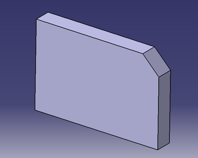
I have a simple CATIA part:

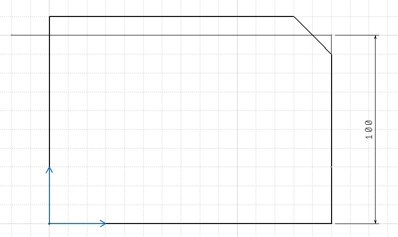
On the drawing I want to measure dimension using some additional point at "virtual" corner:

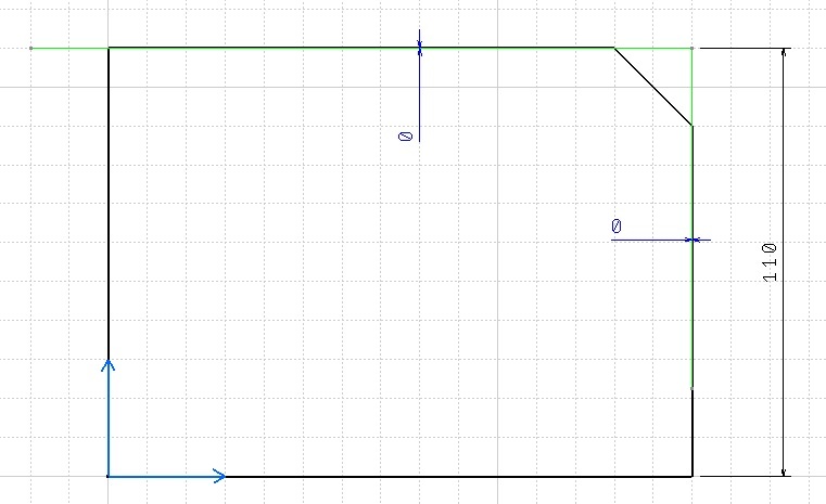
However, if I change one of dimensions, additional line stays in place it was put:

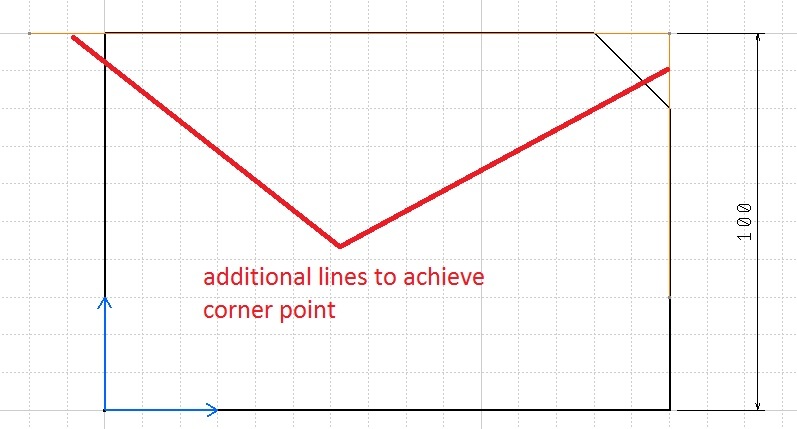
I can draw additional lines to achieve this corner and use drive geometry to make them aligned to part side lines:

Is there any way to avoid this way and use some CATIA built-in features to achieve such result?
Thanks in advance!
I have a simple CATIA part:

On the drawing I want to measure dimension using some additional point at "virtual" corner:

However, if I change one of dimensions, additional line stays in place it was put:

I can draw additional lines to achieve this corner and use drive geometry to make them aligned to part side lines:

Is there any way to avoid this way and use some CATIA built-in features to achieve such result?
Thanks in advance!
