Pekkeri said:
(Mechanical)(OP)28 Apr 20 20:47
Thanks for the answer drawoh!
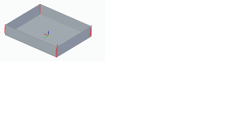
But my point was that it is one part also BEFORE welding! The box is made from single sheet metal piece by bending up the sides (flanges) and then welding the corners.
Who cares? Let's look at the logistics.
I have to build your assembly, so I look down through the BOM. I order each and every piece that has a part number and manufacturer such as McMaster Carr. For each and every piece that has your in-house part number, there should be a corresponding document, and I should be able to pull it out and examine it, and figure out how to acquire it.
[ul]
[li]The part may be an assembly. It will have a BOM. I can read through it and order the parts. [/li]
[li]It may be a specification control. Some manufacturers have weird unmanageable numbering systems. For example, MicroMo has an elaborate system for indentifying their gearmotors. You go to their website or catalogue and construct a long, complicated number that specifies the motor, voltage, gearhead, ratio, output shaft and who knows what else. They give you back an order number which is nice and simple, except that there is no way an engineer can read this and figure out what it refers to. The specification control tells engineering what the part is and it tells purchasing how to order it. In the case of a common part like a fan, the specification control may contain a list of acceptable parts.[/li]
[li]The part is to be fabricated by a subcontractor. The part may be a very simple, rectangular bracket with two holes in it. It may be an elaborate assembly with features welded, pressed in, riveted, or maybe even screwed together. The drawing may have multiple sheets, and it may have a BOM.[/li]
[/ul]
A lot of big manufacturers assign their own part number to everything on the BOM. The drawing either is an assembly, a fabrication drawing or a specification control.
I use SolidWorks. Unless my part is absolutely dead simple, I create an assembly model. I attach the fabrication drawing to the assembly model, and I attach the assembly model to the intended assembly. When I need thread inserts, dowel pins or welded-on features, I add them on and attach a BOM to the fabrication drawing.
--
JHG