Continue to Site

Eng-Tips is the largest engineering community on the Internet

Intelligent Work Forums for Engineering Professionals

  • Congratulations KootK on being selected by the Eng-Tips community for having the most helpful posts in the forums last week. Way to Go!

Drawing verification

Status
Not open for further replies.

Sa-Ro

Industrial
Jul 15, 2019
273
Hi

As per ASME Y14.5:2018

Refer attachment.

Design requirement

1) Datum A will contact with mating part.

2) 2X Dia 4.5 holes (datum B) are used to locate and mount the part.

3) Axes of 15 X 20 slot to be aligned with center plan of dia 5.5 holes (datum B)

4) Outer surfaces 45, 24, 11 are equally disposed from center plane of dia 5.5 holes.

Did I communicated thru GD&T correctly?
 
 https://files.engineering.com/getfile.aspx?folder=91faf196-f8b4-4659-8c1c-ec87bed16c9d&file=Guide.PDF
Replies continue below

Recommended for you

Without an FCF relating the two holes used as datum feature B tot each other it's going to be a problem. They aren't a width so there is no mid-plane.
 
How to specify? Please guide.
 
33 basic
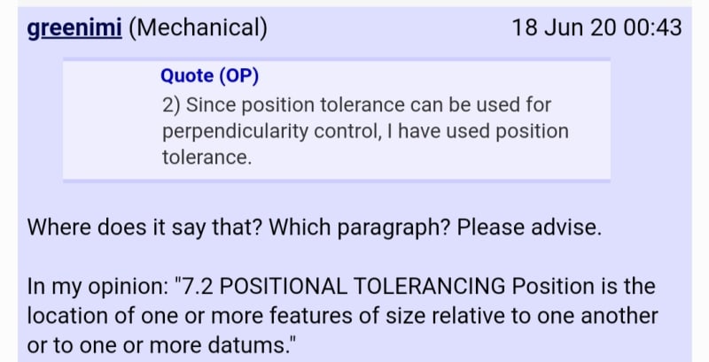
position instead of perpendicularity on datum B
 
Kindly refer my earlier thread: profile tolerance for location control

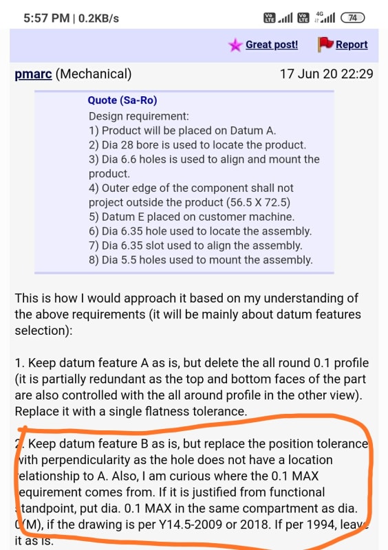
Pmarc and you have suggested to change the datum B from TP to perp. Since there is no location from datum A.

IMG_20200622_175942_cpe73f.jpg


IMG_20200622_175901_mrfnzr.jpg


Based on that guidance now I have provided perp instead of TP.
 
Sa-Ro,

With all due respect I think you samehave some selective hearing.....

Read also my explanation on why perpendicularity was needed there and you will find out if it's applicable here or not.

 
I am unable to differentiate.
 
Only difference I can notice is

Earlier drawing, single hole, only size dimension. No location dimension. Reference to datum A only for perp.

Here two holes, size dimension and location between two holes (not related to any datum). Reference to datum A for perp only.
 
Sa-Ro ... In that other thread, you had one hole as datum feature B. A single hole and the plane it intersects have only an orientation relationship, not location.
In this case your datum B is created from two holes. So while those two holes still don't have a location relationship to datum A, they do need to be controlled for location relative to each other (using the position symbol, not merely traditional ± tolerancing).

John-Paul Belanger
Certified Sr. GD&T Professional
Geometric Learning Systems
 
OP said:
Only difference I can notice is

Earlier drawing, single hole, only size dimension. No location dimension. Reference to datum A only for perp.

Here two holes, size dimension and location between two holes (not related to any datum). Reference to datum A for perp only

You got it.
Single hole: perpendicularity
Multiple holes: position (you put 2x near the size dimension, meaning the pattern creation "mechanism" invoked)
Position will be able to establish a mutual relationship between the holes.
 
Ok.
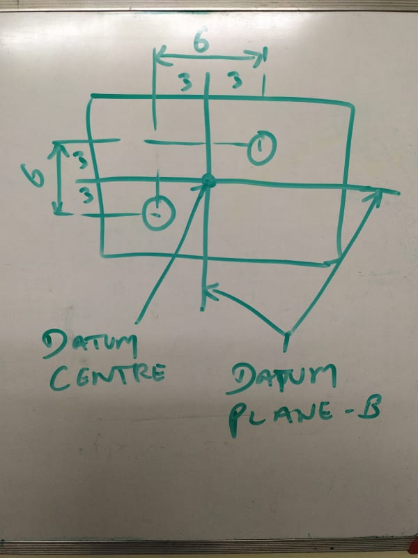
Where will be the datum B plane?

In between two holes?
IMG_20200622_190607_wspt6j.jpg


What about equally disposed from datum B?
 
As mentioned in my drawing, wrt datum A B, other features (45 and 11) are equally disposed from datum B?

 
That would be defined by the basic geometry and the datum feature/simulator relationship, as well as the type of tolerance applied.

The tolerance zones for the 45/11 widths are symmetric about the simulators for B, as defined by the basic geometry. The actual features can be anywhere within their respective profile tolerance zones to |A|B(M)| (satisfies simultaneous requirements too, actually) and since B is modified at MMB the part can shift depending on the amount that the datum features B depart from their MMB.
 
Sa-Ro,

I have general comments about your drawing...
[ul]
[li]I agree with the others that you need a positional tolerance on your 4.5mm holes.[/li]
[li]I like zero positional tolerances at MMC/MMB, but I make a point of specifying a sloppy maximum diameter. The ISO H14 tolerance is +0.3/0mm. The fabricator must make an oversized hole to allow for positional error, and allow for drill tolerances. You have not provided much room.[/li]
[li]33mm is a basic dimension, especially if you use positional tolerances as recommmended elsewhere.[/li]
[li]The notation "TYP" is not part of the ASME Y14.5 standard. Typing in the quantity of features sometimes is a pain, but it explicitly controls all the features. It is good practise.[/li]
[/ul]

A couple of practical notes...
[ul]
[li]Machine shops systematically clean up sharp edges, even if you don't tell them to. When you demand accurate chamfers on both ends of a hole, you may be forcing an additional machine setup.[/li]
[li]You are calling up datum[ ]B at MMC/MMB. This complies with ASME[ ]Y14.5, but just how much of a bonus are you offering? If I use an FOS as a datum feature, I try to select something accurate. Datum[ ]B is way more meaningful if you open up the holes as I noted above.[/li]
[li]When I call up chamfers, my preferred method is to show the two linear dimensions, and configure the view so that the chamfers are controlled by a profile tolerance. My next choice is to use SolidWorks' chamfer specification. If a feature is controlled by an FCF somewhere, the angle specification should come from the datum feature. What you have done is not wrong, but I consider it ugly.[/li]
[/ul]

--
JHG
 
Status
Not open for further replies.

Part and Inventory Search

Sponsor