Continue to Site

Eng-Tips is the largest engineering community on the Internet

Intelligent Work Forums for Engineering Professionals

  • Congratulations KootK on being selected by the Eng-Tips community for having the most helpful posts in the forums last week. Way to Go!

DRF establishment with an inclined hole as a datum feature

Status
Not open for further replies.

Woosang

Aerospace
Dec 18, 2009
48
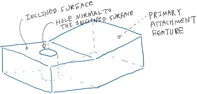
Below is my study on DRF establishment (for CMM inspection) of different datum options when we want to make a hole a datum feature which has an angle with primary datum plane.
Like to here thoughts from the experts if my understanding is correct.

Overall shape of my part looks like this.
2023-10-11_15_06_10-Window_t1d3yp.png


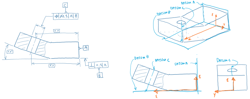
Option 1: Planar primary - Planar secondary - Axis tertiary
2023-10-11_15_09_21-Window_ednkwh.png


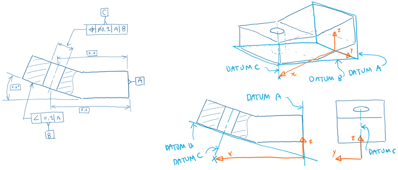
Option 2: Planar primary - Planar (inclined) secondary - Axis tertiary
2023-10-11_15_09_46-Window_r5ihq6.png


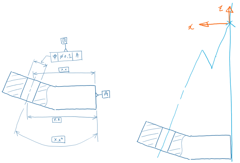
Option 3: Planar primary - Axis secondary
This option locates the DRF far away from the part.
2023-10-11_15_10_04-Window_xunxx1.png


Thanks,
Woosang
 
Replies continue below

Recommended for you

All options look legitimate.
The functional consideration should drive the choice - which option captures the actual assembly constraints?
 
Options 1 & 2 are ok. 5 degrees of freedom are controlled so the zone can only translate along one direction. C only controls 3 degrees of freedom so the tolerance zone could rotate along an axis normal to A or translate parallel to A. It seems unlikely for this to be desirable.

Ryan.
 
Ryan,
Note that in the third option the hole is labeled as datum feature B, so it will likely be used as a secondary datum reference and impose constraints for other geometric tolerances that will control the rest of the features.
It is a usual practice to control the secondary datum feature hole relative to the primary planar datum feature in 3 DOF only.
 

Burunduk said:
All options look legitimate.
The functional consideration should drive the choice - which option captures the actual assembly constraints?
Consideration on assembly condition should be studied by the design engineers. I would just tell them the possible options for datum selection.
As you said, option 3 is legitimate too. But would it be practical for CMM inspection, because the local coordinate system is so far from the part?
 
Woosang said:
But would it be practical for CMM inspection, because the local coordinate system is so far from the part?

It is recommended to differentiate between the datum reference frame as established according to the principles shown in ASME Y14.5 and the inspection axis system. The inspection axis system is based on the DRF, but it can be conveniently located at some agreed upon and fixed translation and rotation relative to the DRF - essentially it simply needs a constant relationship with the datum feature simulators (fixture or the virtual planes and envelopes created digitally).

The standard on measurement and reporting ASME Y14.45-2021 addresses this the following way:

"3.32 REPORTING COORDINATE SYSTEM
reporting coordinate system: a set of coordinate axes relative to which data is reported. A reporting coordinate system may be a simulated datum reference frame that is specified by a feature control frame. It may also be a coordinate system that has been rotated, translated, or both rotated and translated using basic dimensions relative to the specified simulated datum reference frame. A reporting coordinate system may be used to enable reporting of location components for position tolerances.
A reporting coordinate system may also be constrained only by measurement data for considered features
."
 
They are all missing a qualifier for datum feature A.

If the proportions are representative the inspection will be sensitive to slight variations between A and B or A and C.

In all options the top axis dimension to the intersection with the uncontrolled top surface is ambiguous.

It is difficult to pick three non-coincident/non-parallel surfaces/surface pairs/surface groups/axes/axis groups and not control 6 degrees of freedom, so picking at random within that restriction will provide a solution.

Until datum references are specified in a Feature Control Frame there is no DRF, no CSYS.

The design engineers need to pick the constraints before all other design steps to fix the interaction with mating parts.

CMMs are numerical, no doubt using IEEE 754 which has a range of −9.999999×10^96 through 9.999999×10^96, so it will be fine.
 
Woosang,

It looks like your question is about a theoretical part, which is perfectly fine. I want to point out that next time please include the standard the part should comply to, like ASME Y14.5-2009 for instance.

Looking at the part, the full DRF should be | A | B | C> |, where `>` stands for the Translation Modifier, which was introduced in the 2009 version. So if you use 1994 version, they would most likely simulate the part as if there is a translation modifier anyway.

Without the mating part(s), it is not possible to know the function of this part. So maybe the hole should be a slot instead?

The default coordinate system is your option 1, where the zx plane contains the axis of the hole. With just | A | B |, you already have the 2 planes (xy and yz), and 5 DoF constrained. The hole (datum feature C) will determine the origin of the coordinate system, and will also constrain the last DoF.

However, you could change and make own coordinate system. Because the dimensional report will be the same no matter what the coordinate system is.
 
Status
Not open for further replies.

Part and Inventory Search

Sponsor