Hi there. I am new to bridge design and would like some assistance. I am designing a multi column bridge pier with continuous footing supported on drilled shafts. I am using RC Pier and hand calculations in my design. I have designed the cap, columns, and footing and am moving on the drilled shafts. RC Pier does not design drilled shafts with footing, only if they are directly supporting the columns. So I am a little stuck on how to do the drilled shaft design. I am using FHWA-NHI 18-024 Chapter 12 as a guide. I have calculated the loads (Mxx, Mzx, and axial load) at the center of the footing, but how would I resolve the moments to find the Mu at the top of each drilled shaft? Also, any free programs that do drilled shaft design or generate interaction diagrams for circular columns based on AASHTO? Any assistance is appreciated. Thank you!
Navigation
Install the app
How to install the app on iOS
Follow along with the video below to see how to install our site as a web app on your home screen.
Note: This feature may not be available in some browsers.
More options
Style variation
-
Congratulations TugboatEng on being selected by the Eng-Tips community for having the most helpful posts in the forums last week. Way to Go!
You are using an out of date browser. It may not display this or other websites correctly.
You should upgrade or use an alternative browser.
You should upgrade or use an alternative browser.
Drilled Shaft Design help
- Thread starter PAK_ENG
- Start date
- Status
- Not open for further replies.
Answer to your first question, since you have calculated the total forces from the superstructures, now just distribute the loads using P/A ± My/I, in which A represents the number of drilled shafts, and I is the moment of inertia for the drilled shaft group. I am not aware of programs that perform the task you are looking for, so no comment for that.
Another way to distribute the loads is placing the column reactions on the continuous beam (shaft cap), assuming the drilled shaft as supports, and perform continuous beam analysis to get reactions for each drilled shaft.
Another way to distribute the loads is placing the column reactions on the continuous beam (shaft cap), assuming the drilled shaft as supports, and perform continuous beam analysis to get reactions for each drilled shaft.
- Thread starter
- #3
Thanks for the help, Retired13. I would like to get Pu and Mu values at the top of the drilled shafts to use in an interaction diagram. How do I go from the P, Mxx, and Mzz at the center of the footing to those values? I was using P/A + My/I to calculate the Pu at the top of the drilled shaft, as if I were calculating pile loads. But not sure how to go from transverse and longitudinal moment at center of bottom of footing to the Mu needed at top of drilled shafts. Thanks again!

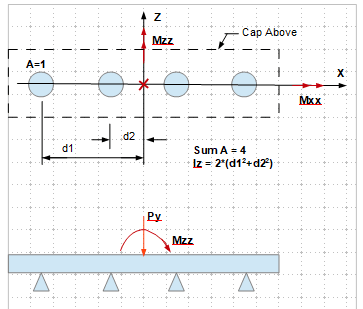
Assume the cap is rigid. For each of the outer shafts the loads are:
Fy = Py/4 ± Mzz*d1/Iz
Hx = Px/4; Hz = Pz/4 (Px & Pz are lateral forces along the respective axis, not shown on the graph)
Mx = Mxx/4
Do the same for the inner shafts, replace d1 by d2.
- Thread starter
- #5
So lateral loads and moment at the top of each drilled shaft is just the total moment or total lateral load divided by the number of drilled shafts? How different would the results of the continuous beam analysis mentioned above be? I suppose I will have to do both and compare. Thanks for the help, Retired13!
BridgeSmith
Structural
We (at the DOT bridge design section) typically make the assumption that the soil around the footing provides lateral resistance sufficient to mitigate the shear from the column. Therefore, there is no moment applied to the drilled shafts in a configuration such as yours. The drilled shafts are assumed to carry axial load only. We've checked the lateral soil resistance vs. lateral shear for enough of our footings to convince us that this is a valid assumption for the configurations we use.
Rod Smith, P.E., The artist formerly known as HotRod10
Rod Smith, P.E., The artist formerly known as HotRod10
- Thread starter
- #8
If your Mxx moment is large, then you need to think about how the load gets into the pile tops.
The only transfer mechanism is through torsion of the cap. If the cap is relatively thin, then it needs to be designed for this torsion and you need to design to resolve this torsion and get it into the piles.
If the moment is small and the cap is massive, then maybe it's resolved into the soil and the piles are essentially axial only.
- Status
- Not open for further replies.
Similar threads
- Replies
- 4
- Views
- 1K
- Replies
- 5
- Views
- 1K
- Replies
- 15
- Views
- 7K
- Locked
- Question
- Replies
- 5
- Views
- 1K
- Locked
- Question
- Replies
- 2
- Views
- 2K
