Eng-Tips is the largest engineering community on the Internet

Intelligent Work Forums for Engineering Professionals

Drilled Shaft with Both Permanent and Temporary Casing 1

Status
Not open for further replies.

STrctPono

Structural
Jan 9, 2020
703
0
0
US
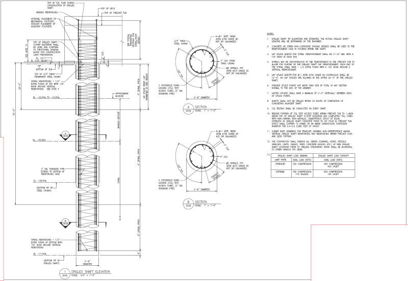
I have a job currently being bid on. New concrete pier in the ocean. 2'-6" drilled shafts (yes, you heard that right, not driven piles). Our shafts are 72ft long with 28ft long permanent steel casings... coral at 69ft deep. Temporary casing is optional if Contractor wants.

RFI came in during bidding. RFI asks, "can Contractor oversize the permanent casing to allow extraction of the 3'-0" ID temporary casing". I discussed it with Geotech and told him that I do not want the shaft oversized as this affects structure behavior and affects the precast superstructure elements. He responded back to the RFI that shafts cannot be oversized and that this is a means and methods issue. Seems a bit of a cop-out answer, but, oh well.

That means the Contractor was thinking that they could extract the temporary casing on the inside of the permanent casing? Forgive my ignorance, but is that how you typically withdraw a temporary casing when it is below a permanent casing? Geotech seems to think the more logical way is to advance the permanent casing down to the depth required to satisfy constructability and then withdraw permanent casing back to the final elevation during concreting. Does this seem more logical.

I was hoping to get your guys' input on the matter.

Thanks.
 
Replies continue below

Recommended for you

I have seen oversize temp casing used to install permanent casing of nominal pile dia. Concrete is placed in the permanent can with some material placed around the bottom to ensure that the concrete does not float the permanent casing during filling. Let cure overnight and pull the oversize temporary casing the next day as backfill is placed in the annulus between the temp and perm casings.
 
Thanks for the insight. I'm afraid filling the annulus would be very difficult, and something I have zero confidence that they could do correctly.
 
STrctPono,

I don't know what the RFI was asking if you are quoting accurately.

With regard to my response above, the annulus could be filled in a few ways that I can think of - tremie placement of cementitious material, likely low-strength, or placing uncompacted sand either free-fall or slurried. Typically the temporary casings are 6-12 inches larger in diameter than the permanent.
 
You really should provide a sketch or detail for the proposed drilled shafts. From the above discussions it is unclear, at least to me, what the requirements are for the permanent casing pipe. Must it be drilled partially into the coral bedrock? I assume that the permanent casing extends above the ocean's high tide. I assume that there is soil (sand) overburden above the coral. If so, as jdonville said, an oversized, temporary casing pipe is usually needed to allow drilling the rock socket.

 
Sorry if I was not clear. See attached drawing.

Untitled8_qhy1js.png


jdonville, Drilled shaft is in the water. Filling the annulus of the extracted temporary casing with a grout introduces all sorts of issues. Environmental concerns for leaking grout. Needing to add a VMA to the grout mix since underwater. Possibility that the annulus is not completely filled. Since this is coral, they may be pumping grout for days if they hit a large void in the coral. I paraphrased the RFI but, yes, it asked if they could oversize the permanent casing so that they could extract the temporary casing from the inside of the permanent casing. They are worried that they are going to hit large voids in the coral and use an unnecessary amount of concrete during the pour. We are already paying them for 100% overpour quantity for this very reason.

jdonville said:
Typically the temporary casings are 6-12 inches larger in diameter than the permanent.
Thanks!

PEinc said:
what the requirements are for the permanent casing pipe. Must it be drilled partially into the coral bedrock? I assume that the permanent casing extends above the ocean's high tide. I assume that there is soil (sand) overburden above the coral. If so, as jdonville said, an oversized, temporary casing pipe is usually needed to allow drilling the rock socket.
Yes and yes. But the Geotechnical Engineer of Record is saying that the more prudent option would be to advance the permanent casing down to the bottom of the drilled shaft and then extract it back to elev. -28.00 while they are pouring the drilled shaft concrete. I have never seen this done but wanted to see if this is also typical.
 
Im am with PEinc, I still dont understand exactly what is proposed. I cant see from the drawing either, can you upload it as a file that I can download and zoom in on.

Also, if you are afraid of large voids beneath your pile, casing issues are the least of your worries! We encounter voids / cavities in some of our project. We undertake geophysics to get a better handle of the issue. If piles are proposed, we monitor concrete consumption. If consumption is more than 25% more than theory then we grout around the pile.
 
To do what the engineer is proposing, the contractor would need a very large drill that is similar to a duplex rotary or rotary percussive tieback drill - but one that is capable of drilling much larger diameter holes than required for tieback or tiedown anchors. At the same time that the drill is installing the permanent casing pipe, there is an inner drill steel with either a down hole hammer or a roller-cone bit which will clean out the soil and then drill the rock socket as the casing is advanced. Once the rock socket has been drilled, the inner drill rod and bit or hammer are removed, the concrete and reinforcement are placed, and then the permanent casing pipe gets pulled up to or near the top of the rock socket. In the Pennsylvania/New Jersey/New York area, Ziegenfuss Drilling, Inc. ( does this type of drilling with a Barber DR24 drill rig. However, there may be some limitation on the hole diameter size or equipment availability.

 
Here is the plan sheet as a link.

Thanks PEinc for the insight on the type of drilling. Your description of advancing the casing while using a down the hole hammer or roller-cone bit and then withdrawing the permanent casing is exactly what the Geotech mentioned as being the most prudent drilling option.
 
 https://files.engineering.com/getfile.aspx?folder=ab26fe07-16fc-4ef5-b86d-802f257832ae&file=12-02-19_LBH_RVSD_BID_PDF_(00000006).pdf
I don't know anything about drilling in coral so my questions are:

1. Is coral bedrock stable enough to allow open hole drilling techniques? If not,
2. Can casing be spun down through 15' of overburden and 46.5' of coral bedrock? If, not...

Then these piles could be difficult to install. Sometimes the driller can work the casing down by spinning until refusal, excavating the material inside the casing, then spinning the casing down further, and repeat. There are some conditions in which the casing won't advance anymore, so that's a concern with not allowing them to use oversized temporary casing. If the contractor is mandated to only use one piece of casing and the casing hits refusal early with 30' of stickup, that's a huge issue since they won't be able to get an auger down to pull out material. The casing will have to be cut and then field welded (if allowed).

I agree that if there is an annulus between the oversized temporary casing and the permanent, as previously mentioned, grouting the annulus before casing extraction should be fine. If you're worried about the coral losing the grout maybe some re-grout tubes could be installed?

Hopefully whoever wins the bid knows what they are doing, especially if the engineer is not allowing the use of oversized temporary casing.
 
PEinc,

Precast concrete U-shape tubs for the superstructure drilled shaft caps. Precast deck panels and topping pour above that. Precast items will keep everything dry for the CIP sections. Tub walls are designed for wave force. temporary supports for the concrete tubs, however, is on the Contractor.
 
STructPono,

Unrelated to your question, but why do you show spiral and hoop reinforcing (which also appears discontinuous with the spiral on the cage below top of pile) extending above the top of pile?!
 
Jdonville,

The spiral/hoops above the top of shaft is typical joint shear reinforcement, helps to create a more ductile behavior in that joint, and allows me to reduce my development length of the vertical bars, thus allowing the shaft cap to have a slimmer profile.

Since the shaft cap is pretty congested with reinforcing coming in at orthogonal directions near the top of the cap, I opted to go with the single piece hoop as opposed to the spirals as this will make installation of the reinforcing steel much easier on the iron workers.

Some designers show the spirals continuous through the top of the shaft, but in the past it has created headaches for me with RFI's and site visits since they can never fit the bottom layer of reinforcing in and always requires in-field modifications.

Thanks for all the advice.
 
Vertical reinforcing protruding from top of shaft into the cap maintains a circular layout so the closed hoops are also circular. The drilled shaft cap, however is rectangular in shape.
 
Then I don't understand what warrants wrapping the vertical bars above the top of pile with confining steel. Presumably, the reinforcing steel for the pile cap should handle the load transfer to/from the vertical bars, no?
 
Status
Not open for further replies.
Back
Top