Continue to Site

Eng-Tips is the largest engineering community on the Internet

Intelligent Work Forums for Engineering Professionals

  • Congratulations KootK on being selected by the Eng-Tips community for having the most helpful posts in the forums last week. Way to Go!

Drossbach Ducts - Precast Concrete Panels 1

Status
Not open for further replies.

TS_NZ

Structural
Nov 14, 2021
1
Hi Team. One of the issues I have been encountering in New Zealand is the detailing of precast panels on drossbach ducts. NZS3101 (concrete code) does not seem to provide much help in this case and I see a lot of engineers reference the detail from SESOC Interim Design Guidance, where you have to provide confinement to ALL the ducts.

I do understand that these are the areas subjected to stress reversal, but it seems overkill to provide hoops around the ducts outside compression regions, considering the fact that we are limited to nominally ductile loads due to shear-friction provisions. Furthermore, it seems there is a good degree of confinement for the bars outside the compression zone region, provided by the links between the horizontal rebars.

It would be great to get some feedback from the practicing engineers justifying it one way or the other. There has been a bunch of tests done here in NZ illustrating that the confinement helps for panels to undergo quite high ductilities, but again, we would rarely design these panels to be anything but nominally ductile.

Regards
Tim

 
Replies continue below

Recommended for you

This previous discussion is probably relevant
Not all walls will have or require links between both layers from a code detailing perspective for confinement, for a wall that meets the nominally ductile curvature limits (off the top of my head) there is no requirement to provide these cross links in the mid regions.

For a singly reinforced wall my preference is to utilise grout sleeves (less grout, don't need the recommended confinement reinforcement for laps)

But you will require these closed stirrups (thats what stirrup-tie means in the code) when lapping in reversing stress regions as per clause 8.9.1.2 [edit & 11.4.8.2] that's what the interim sesoc guidance check is actually checking. The drossbach is inherently a lap with some tube between.

UoA have done a bit of research and testing to justify in recent years which you may have come across previously?

 
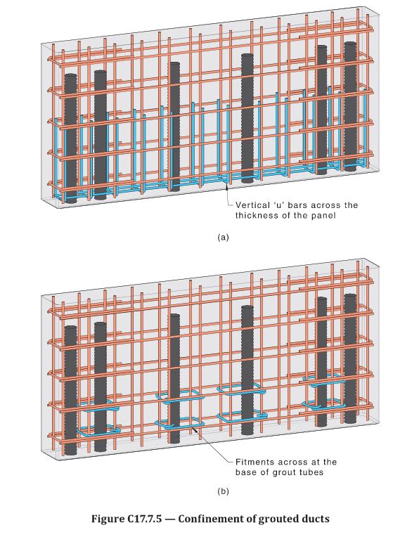
Worth noting that the commentary now clarifies, at least partially, what the detail would look like. My understanding is the detail can be achieved by usign closed ties (as we have discussed in the old thread and as specified in the NZ commission guide) or by using U-bars,as per below image. Unfortuntely, there's no clarification on how to calculate teh required area of these U-bars or closed ties. I htink I'll keep using the rule in teh NZ document.

Capture_diu8ex.jpg
 
The vertical ubar detail doesn't really provide any confinement at all to the duct and the bars lapping with the duct, I wonder what the justification was for suggesting the details were equivalent?

NZ detail effectively requires the confinement over the full length of the connection (and provides an equation to evaluate the required closed tie diameter), not just as implied 'at the base', hopefully that requirement is quantified?

 
Agree with you, Agent666.

Reading the commentray clause (also attached below) I am inclined to think that these detailes are not equivalent, they do different things and one should not substitute the other one and they should be both used at the same time. Not very clear on this though, first uses the word OR, then usses OR/AND... quite confusing. So I exepct almost every engineer in Australia to just use the U-bar detail as it will be cheaper and easier.

Capture_lzzss6.jpg
 
Agent666 said:
The vertical ubar detail doesn't really provide any confinement at all to the duct and the bars lapping with the duct

The way I read it is that AS3600 is not trying to provide confinement to the full length of duct. It is providing reinforcement at the base of the panel for a splitting failure, which both details will provide.

I find the comment about the erection packers interesting. In my experience they are always left in place. I do not see how they can be safely removed.
 
But the transfer of load (i.e. the 3D strut and tie mechanism they refer to) occurs over the full length of the lap/duct. I don't disagree with the splitting is likely to initiate at the base where the stresses are higher, but just providing the reinforcement at the highest stress points may not cover the same splitting occurring further up the panel.

The rules in NZ are an extension of the normal closed links required around normal laps in regions of reversing stresses where bar stresses exceed 60% of fy. So it is just a particular specialised use case already covered by our underlying code rules. I guess because Australian code is kind of half-baked on seismic, contemplating going full hog ACI or NZ code is too much for Aussie engineering industry to deal with.... that old we've done it this way for so long we cannot change mentality seems well entrenched and the lack of general knowledge on why things are done the way they are for seismic seems to be really lacking in the general engineers pool of knowledge. If anything's going to find the weaknesses in your detailing/design it's going to be a severe earthquake.


Don't think they are saying the packers need to be removed, more that if poorly grouted it is an issue potentially, so make sure your QA ensures ducts and panel gap is correctly grouted. We've had jobs where we required contractor to measure grout volumes to prove grout tubes/drossbach ducts are adequately filled, and no grout loss has occurred. They hate it because it forces a high level of quality than they might be used to, but likewise we have not had a single issue with partially grouted ducts since insisting on it.


hi agent666, you mention grout sleeve above - can you elaborate on what these are? or are you refering to the Reid product? I did try to use the Reid product a few years ago but couldnt due to them being cast-iron and thus not ductile.
 
Yeah that's what I mean. They are made out of ductile cast iron, it's not your brittle cast iron of yesteryear.

I know Reid have some data on it, but been years since I looked at it but I believe they proved they can resist close to the upper characteristic strength (I.e. 95% characteristic strength). I cannot recall if they were fully complaint with all the mech splice provisions in code however. If in doubt talk to Reid rather than go off my hazy memory.

But for singly reinforced walls which I was referring to in the context of my statement, I wouldn't be reliant on any ductility in this application. In NZ code you're effectively designing singly reinforced walls for mu = 1.0 with the lower strength reduction factor for in plane actions (being phi=0.7). You should not be using singly reinforced walls for any ductile application (>1.25).

 
Agent666,

The latest AS3600 has a similar limitation for singly reinforced walls, mu = 1.0 only.
 
Status
Not open for further replies.

Part and Inventory Search

Sponsor