Eng-Tips is the largest engineering community on the Internet

Intelligent Work Forums for Engineering Professionals

Dry in Wyoming, need waterline help to water cattle 5

Status
Not open for further replies.

carter livestock

Agricultural
Jul 26, 2022
9
0
0
US
Hey all, I am rancher in Wyoming. We raise and market some of the most nutrient dense grass finished beef in the US, Carter Country Meats. We operate a regenerative grazing strategy to build our soils. We have been extremely dry this year and our natural springs and water sources will not be able sustain our herd with existing infrastructure. I am asking for help designing the following water system

My Plan is to pump water from a large reservoir to different locations on the pasture. Once the area is grazed we would like the flexibility of moving our water tank and line to a fresh area. I am looking for help in sizing a pump and designing the system.
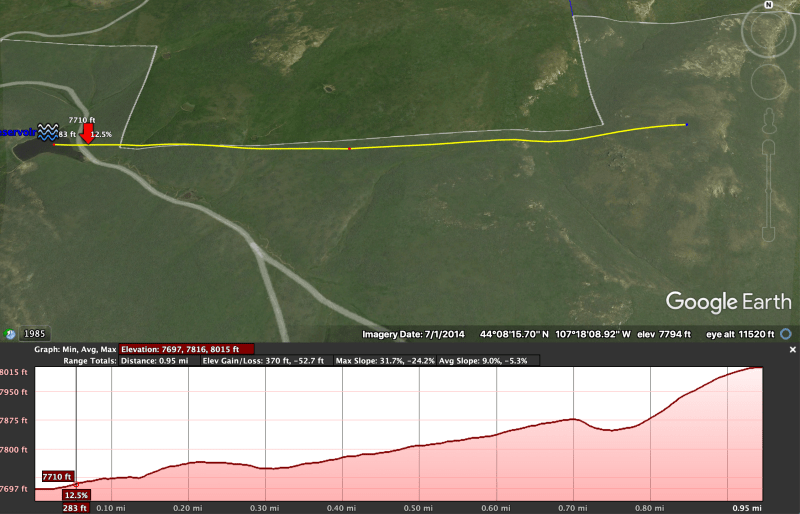
Max distance to pump: 2miles
Elevation difference: 400ft higher than pump
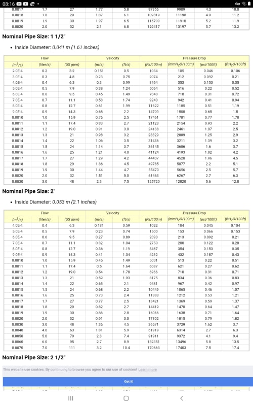
Volume: 50gpm
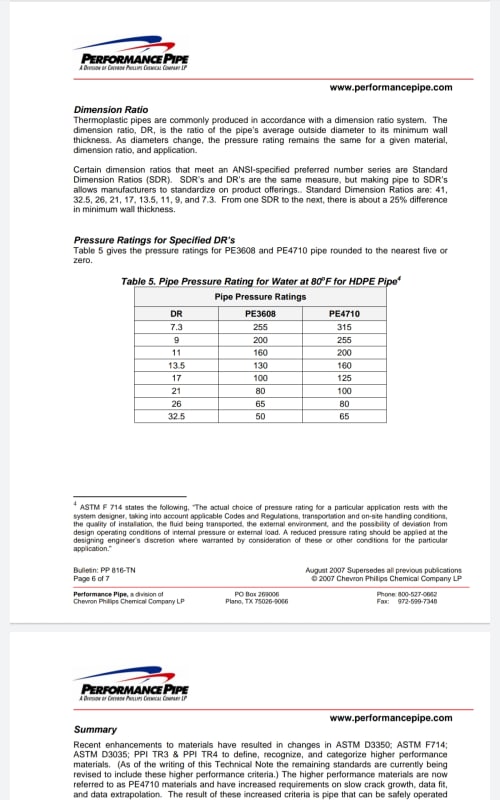
Pipe Diameter. 1 1/2" poly pipe
Fuel source: gas/diesel
pipe fittings: butt fuse

Ideally, i would like to have an inline pressure switch that would trigger the pump to turn on when the water drops below targeted pressure, which would be initiated when cows begin to water. We use float valves on water tanks to conserve water. Vice versa, when the cows stop drinking and the tank is full, the float valve closes, building pressure and shutting the pump off. I don't know if this is possible and would appreciate your help


Replies continue below

Recommended for you

Just a couple quick comments to get you started:

A 1.5" diameter pipe is too small for this application. At 50 gpm, the flow velocity would be about 9.1 feet per second (fps). Please note that since I don't have the true inside diameter for your proposed pipe, I am assuming for my comments here that actual = nominal. For water distribution systems, I usually target 3 to 6 fps at peak flow, but I'm also not dealing with such a long pipeline. Since head loss is proportional to the square of the velocity (per Darcy-Weisbach) or the velocity to the 1.85 power (per Hazen-Williams), velocity matters a lot.

Here's how much it matters for your situation: for 2 miles (10,560 ft) of 1.5" pipe, assuming Hazen-Williams C=145, and not including minor losses, the total head loss would be 2,134 ft! Adding another 400 feet for the elevation difference, and your pump discharge pressure would be an unrealistic 1,098 psi.

On the other hand, a 4" pipe would result in 18.0 feet of head loss and a velocity of 1.28 fps. With 4" pipe and the assumptions above, the pump discharge pressure would be 181 psi. This is doable, although you might consider pumping to a permanent intermediate tank, then pumping from there to your movable tank. This would require a second pump and a second electrical service (solar power, perhaps), but total energy usage would be nearly the same and you could use a thinner wall pipe since the pressure would be lower. On the other hand, thicker wall pipes may be desirable for durability.

All that being said, I think you need to consult an engineer in your area who has experience with these types of projects.


============
"Is it the only lesson of history that mankind is unteachable?"
--Winston S. Churchill
 
In addition to fel3's pipeline diameter advice, we should point out that the devil is in the details and that hydraulic systems are very sensitive to topography, making it difficult, but not necessarily impossible, to accommodate movable discharge points. That, as well as possible control and air release valve locations depends on the elevation profile of each potential pipeline route. You will need an elevation survey of each of all potential pipe routes. A 400 ft elevation difference may require a completely different design depending on exactly where that elevation is in relation to the length of the pipeline and whether the slopes of the terrain inbetween is uniform or variable. If you can provide the latitude and longitude of your pump location and preferred discharge points, we may be able to offer more specific design advice.

If there is a county agricultural extension service office near you, they may also be able to assist you with advice and general information taylored to your specific location.

Einstein gave the same test to students every year. When asked why he would do something like that, "Because the answers had changed."
 
I think you really need to do a bit of thinking about your demand and requirments and then contact an irrigation company like this one
If you want to move between multiple location to spread the water around different drinking troughs.

I would be cautious about your flow control. If you don't have a BIG accumulator which can fill up and pressurise and then release water gently, your pump would either never stop as the cows keep drinking enough to never cause the water level valve to fully close, or it would be turning on and off every minute. Gas/diesel engines don't like stopping and starting like that and neither do electric ones.

So at your end point I would think you need a storage tank or tanker of at least 1000 gals and just control the pumping on level. Below say 1/4 full turn the pump on, turn it off when 90% full and then gravity feed the drinking troughs. Much kinder on the pump and system.

One thing to think about is how you get your water. You might want to think about generating electricity and then using a submersible electric pump or turbine pump fixed to a pontoon which floats up and down and has a flexible hose to the shore. note your 400 ft elevation means you need a pump and pipe with at least 300 psi discharge pressure and probably up to 400 o get any flow. This might be more difficult to find, but is a key parameter to tell everyone about. If you can't get ones so high easily you might need to break the system half way up the hill, but that's a real pita.

Also moving poly pipe about is not easy. Hoses on reels are very common and you will need at least 3" or more for that sort of flow.

As TBE says, maybe just hire some towable tankers, fill them up, drive to your field and then just leave them there, or use them as intermediate tanks.

All depends on on whether you think this is a permanent / yearly thing or just this year.

But these systems are errrr pretty "Agricultural". Best to find a local irrigation company and see what they have available in the yard to sell /hire you and work from there.

Remember - More details = better answers
Also: If you get a response it's polite to respond to it.
 
If I was to scale back what would the numbers look like with these next two scenerio's
.7miles of 1.5" poly or 2" pipe with 200 ft up hill
1 mile of of 1.5" poly or 2" pipe with 300ft up hill
 
Can you make a sketch with desired flows, what's going on and a view of how and where the piping changes height.

If you can't we can not really help you as that's about the minimum needed to make any valid decisions.

You would need find someone local who can help you, starting with creating a document as just described.

Keith Cress
kcress -
 
Lets just keep it simple and say
straight uniform slope up to given elevation from pump to pipeline outlet and
use some polypipe pressure loss tables.

1.5 Diameter pipe with a Flow of 48gpm --> 5.6 psi/100ft
0.7 miles is 3700ft. 3700/100 = 37 Flow Pressure loss is 37 × 5.6 = 207 psi
1 mile is 5280ft. 5280/100 = 53 Flow pressure loss is 53 x 5.6 = 297 psi

Elevation Pressure loss pumping uphill is 0.43 psi/ft
For 200ft uphill = 200ft × 0.43 = 86 psi
For 300ft uphill = 300ft x 0.43 = 129 psi

Add the Flow pressure losses and the elevation pressure loss together for the total pressure loss.

For the 0.7mi long pipeline,
0.7mi with 200ft uphill = 207 + 86 = 293 psi
0.7mi with 300ft uphill = 207 + 129 = 333 psi

For the 1mi long pipeline,
1.0mi with 200ft uphill = 297 + 86 = 383 psi
1.0mi with 300ft uphill = 297 + 129 = 426 psi

Well, those look pretty high. According to these pressure tables, you're not going to get more than 150 psi allowable pressures with PE PN16 pipe at 100°F.


High Density Poly has higher allowable pressures. To 315 psi.
Screenshot_20220730-210125_Drive_p42xrn.jpg

Screen shot is from

You can now run the numbers for the 2" diameter pipeline yourself.

Here are the tables of flow losses for polypipe.
I took the screen shot from this link where you can find other pipe diameters.

Screenshot_20220730-081604_Brave_yr4lkb.jpg


Einstein gave the same test to students every year. When asked why he would do something like that, "Because the answers had changed."
 
1504-33, Thanks so much, what the equation or could you provide the table to find 5.6psi "1.5 Diameter pipe with a Flow of 48gpm --> 5.6 psi/100ft" Id like to figure it for 2"
 
It's up there.
Look in the 1.5 inch pipe table.
In the flow column, find 48gpm (it's the last value down at the bottom of the list).
Follow that line right and in the pressure drop column under psi/100ft you will see 5.6 psi/100ft

2" pipe table is there too.
Flowing Pressure drop for the same 48gpm with a 2" pipe diameter is 1.62 psi/100ft.
For a mile long pipe I get 86 psi flow loss.
You can see the equivalent head loss of 3.7ft/100ft, or about 3.7 × 5280/100 = 200ft.

Add your elevation head options of 200, or 300 ft, to that and you get either 400, or 500ft total head loss.
So your pump will have to provide either that same 400 or 500 ft head at 50gpm.
You will need around 10 Horsepower for the 500ft total head loss option and about 8 Hp for the 400ft head. I assumed a combined pump and motor efficiency of 0.7 Confirm that number before purchase. A cheap pump setup might be as low as 0.5 in which case power will go up by 40 to 50%

You want a 500 ft x 0.43 = 215 psi pump discharge pressure AT 50 GPM. Your pipe design pressure should be a bit over that. Look for something around 225 to 250 psi if you can. Max Pressure typically reduces over the years so go a bit higher than 215 psi. Be sure it is greater than the pump's maximum discharge pressure. Pump max pressure occurs when starting, closed valve, at zero flow.

That profile is certainly uniform enough. You shouldn't have any flow control issues if you can find a pump with those characteristics.

I'd put a check valve at pump discharge to keep pipeline water from backflowing into the pump when stopped. You might also put an on/off ball valve between pump and check valve if you like. You probably won't need a valve at the pipeline outlet, but then again it could be useful at times. You might get a leak in the pipe when you do not want to lose the water in the tank.

Einstein gave the same test to students every year. When asked why he would do something like that, "Because the answers had changed."
 
Would adding an accumulator after the pump and before the pipe ease the pump starting? Put a check valve after the accumulator and a small bleed that closes when the pump is started, to drop the pressure in the accumulator when the pump shuts off. Then the pump isn't starting against full pressure.
 
Starting the pump isn't a problem. Dead heading a centrifugal pump during start-up is actually the ideal condition requiring the least amount of energy.
 
Yours is the first mention that it would be a centrifugal pump - agree that for that kind of pump dead-head is OK. I guess it's assumed that it would be centrifugal rather than positive displacement.
 
No reason to use anything else.

Einstein gave the same test to students every year. When asked why he would do something like that, "Because the answers had changed."
 
Lets not forget that at 8,000ft there is a lot les air pressure as well....

Carter L - I think you've got a lot of info here, but I still think if this is something you need NOW, then first you need to find out what's available in terms of pipe / hoses / pumps and tanks and then try and stitch something together.

A lot of agricultural stuff / basic water pumps and systems are relatively low pressure so you may need to do this in two lifts if that's all you can get at short notice.

Also don't forget to include a trash / fish filter in your inlet otherwise you will be forever pulling pulverised aquatic creatures and weeds out of your system.

Remember - More details = better answers
Also: If you get a response it's polite to respond to it.
 
The solution to ensure a successful outcome is to employ someone who knows what they are doing ie. a reputable pump supplier / company - get it it done right the first time,
It's a very basic application for an experienced pump /application engineer who will:
1. Calculate the total head
2. Select the appropriate pressure rated pipe
3. Size the pump/ driver / control equipment

Deciding on pipe diameter/ cost compared to running costs over time is the only point that requires any real thought.

The pipe pressure rating requirements change as the distance from the pump increases allowing for lower pressure ratings along pipe length.
Code:


It is a capital mistake to theorise before one has data. Insensibly one begins to twist facts to suit theories, instead of theories to suit facts. (Sherlock Holmes - A Scandal in Bohemia.)
 
Pierreick
Good link.

It is a capital mistake to theorise before one has data. Insensibly one begins to twist facts to suit theories, instead of theories to suit facts. (Sherlock Holmes - A Scandal in Bohemia.)
 
Status
Not open for further replies.
Back
Top