Continue to Site

Eng-Tips is the largest engineering community on the Internet

Intelligent Work Forums for Engineering Professionals

  • Congratulations IDS on being selected by the Eng-Tips community for having the most helpful posts in the forums last week. Way to Go!

Dynamic Implicit and Static General step give vastly different results?

Status
Not open for further replies.

drennon236

Civil/Environmental
Mar 27, 2020
102
I have 2 steel cylindrical parts, and in the middle is a concrete cylindrical part. The concrete part is supposed to stop any movement between the parts simply through coulomb friction. The top steel part is moved vertically down 5 m through BC. Below the interaction properties are shown:

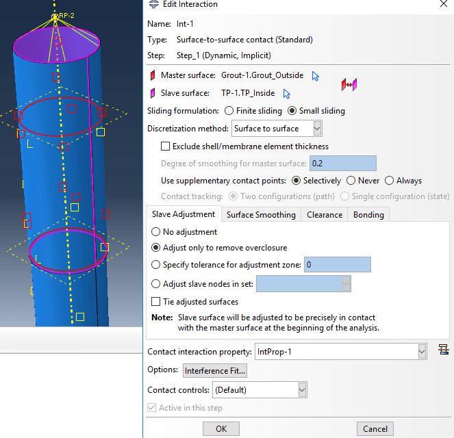
Interaction between concrete (grout) and upper steel part:
Capture_j6z0dx.png

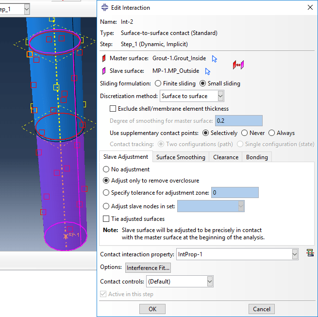
Interaction between concrete (grout) and lower steel part:
Capture1_ffdtig.png

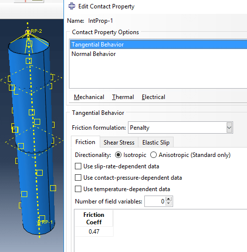
Interaction properties:
Capture2_ufqgro.png

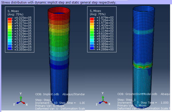
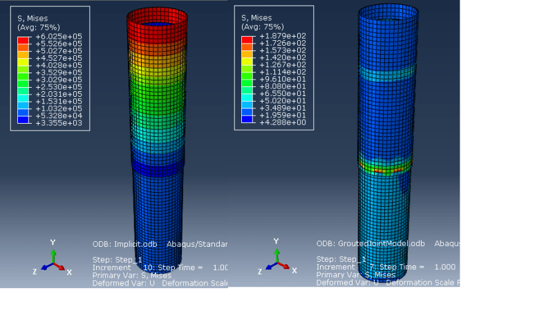
Stress distribution with dynamic implicit step and static general step respectively.
Capture5_cdcra7.png


As can be seen, with the dynamics implicit step, the model experiences significantly larger stress (and stress distribution) compared to the static general. Should the results not be somewhat similar as all interactions are the same for both models? What can be the cause for this difference?
 
Replies continue below

Recommended for you

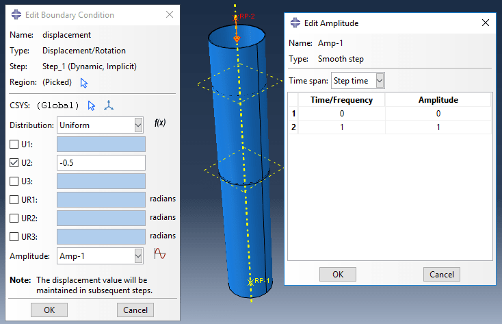
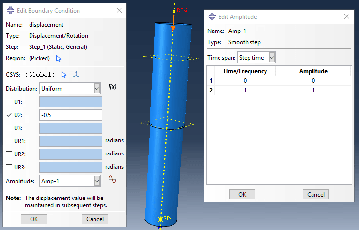
How is the prescribed displacement applied in time (what is specified in Amplitude part of BC definition window in both analyses) ? Do you use quasi-static in implicit dynamics analysis ? Are all units correct ?
 
I am using SI units (m, N, kg, Pa), and I simply copied the model so the units should be the same. I think it is quasi-static, you can see the BC (-0.5 m in the vertical direction), and amplitude (smooth step). The entire model is around 60 m total in vertical length.

For the dynamic implicit:
Capture_q064sv.png

For the static general:
Capture1_nzicey.png
 
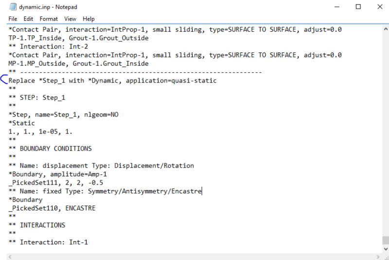
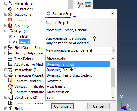
To make sure that both analyses have identical settings try this: copy the input file of static simulation and edit this copy. Replace *Static step with *Dynamic, application=quasi-static. Leave the rest without changes.
 
Is this where and how I edit? I tried a few edits and could not get it to run.
Capture1_bumw7m.png

I also did it within Abaqus as I have not worked much with INP files, is this the same?
Capture_wbf5jp.png


Also do you think most likely the static or dynamic step is the correct one if we cannot figure out why there is a difference? Attached is the INP file.
 
To replace steps in the input file you have to do it manually (delete keyword *Static with its parameters and data lines, place *Dynamic keyword with proper parameters and data lines instead).

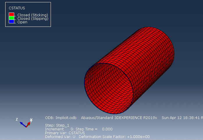
Most likely something is wrong with implicit solution. Check contact output in both analyses (CSTATUS, COPEN, CPRESS).
 
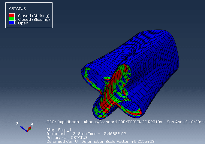
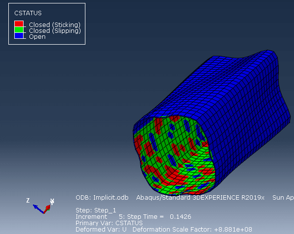
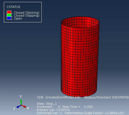
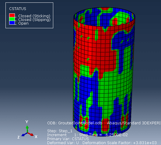
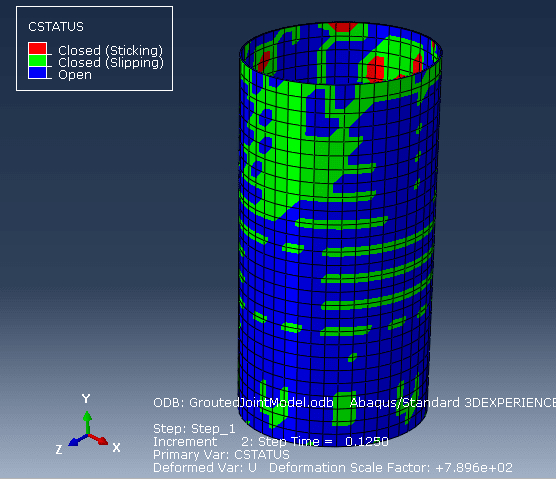
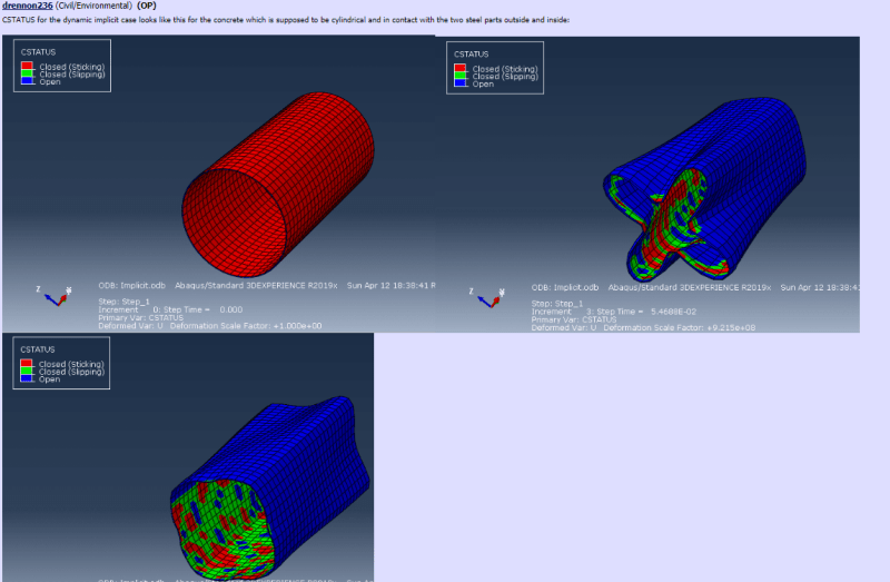
CSTATUS for the dynamic implicit case looks like this for the concrete which is supposed to be cylindrical and in contact with the two steel parts outside and inside:

Capture1_bpijnp.png
Capture_jzwypx.png
Capture2_gv6bsh.png


And like this for the static (which looks more correct and not deformed to my untrained eyes):

Capture3_uwvlet.png
Capture4_x51yxz.png
Capture5_wrt81s.png
 
Deformed shape plots from your dynamic implicit analysis have larger scale factor than those from static analysis, hence the difference in deformations.

Do you use a single solid element through thickness ? You should mesh these parts with more layers.
 
The part is too thin for more layers. I tried to create another circular partition (to have more layers) and mesh, but it did not turn out well. Could I ask why you think most likely something is wrong with implicit solution instead of the static one? And how does the CSTATUS look for the static case?
 
My assumption that the problem lies in implicit solution is based on the picture showing stress distribution that you attached to your first post. It's much more regular in case of static simulation while implicit solution gave irregular stresses with some strange concentrations. But of course I can't say for sure. It's necessary to verify both models. You should check warnings and energies, among others.
 
Static and dynamic contact defaults are different, which is probably where the issue is I think. And just to be sure, the stress distribution is more regular in the implicit? The left is the implicit case and right is the static.

Capture5_wypowu.png


And for the CSTATUS in the implicit case, is it not strange that the nodes on the outside of the concrete cylinder are open while on the inside they are closed or slipping? Because the concrete cylinder is in contact with steel on the outside and inside.
Capture1_mzumpe.png
 
My bad, I don’t know why I thought that these pictures are in opposite order. In such case implicit solution looks better when it comes to stress distribution.

It seems to be an issue with not fully established contact. Try changing the geometry (diameters) a bit to cause small penetration between the parts and enable the option to remove overclosure.
 
Status
Not open for further replies.

Part and Inventory Search

Sponsor