Continue to Site

Eng-Tips is the largest engineering community on the Internet

Intelligent Work Forums for Engineering Professionals

  • Congratulations SDETERS on being selected by the Eng-Tips community for having the most helpful posts in the forums last week. Way to Go!

Dynamic profile Toleranze Zone modifier

Status
Not open for further replies.

Kedu

Mechanical
May 9, 2017
193
Straight forward question:


ASME Y14.5-2018
In order to correcly use dynamic modifier with profile, do we need to have the radius basic or is okay "as-is" (plus / minus)?


ISO
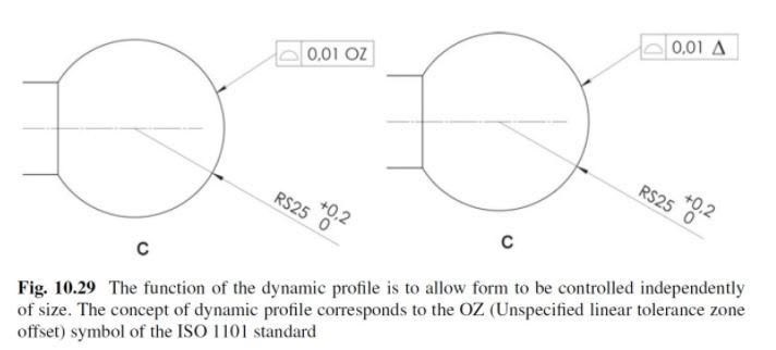
Same question for the OZ modifier.

QST_-_Copy_xbivqz.jpg
 
Replies continue below

Recommended for you

Kedu,

For ASME I would say profile should not be combined with +/- directly toleranced dimensions*. This is true regardless of whether of not a dynamic modifier is applied. The dynamic zone must be progressed "normal to the true profile" - a true profile requires basic dimensions. One could claim that this is not necessary for the shapes which ISO provides exception to below (circles/cylinders/spheres/tori), but the letter of the law requires a true profile for profile tolerance - dynamic or otherwise, and a true profile requires basic dimensions.

For ISO, it seems that basic dimensions may not be required for certain shapes for which the TEF can be scaled the same way regardless of what the nominal size is ie: circles/cylinders/spheres. Interesting they did not include parallel lines/planes, I guess because those are considered two separate features instead of one feature?

ISO 8.2.2.1.4.1 said:
The nominal size of the TEF may not be defined by a TED for circles, cylinders, spheres and tori, e.g. in the case where the there is only a +/- tolerance indicated for the size. In this case, the OZ specification element shall always be indicated for line profile specifications and surface profile specifications to make it explicit that the size of the TEF is not fixed

*Edit - just to add, I want to clarify that I mean that the size/form of the true profile should not be defined with +/- dimensions because of course, that would not be the definition of a true profile. As long as you can fully define your true profile with basic dimensions, it is possible to involve +/- directly toleranced dimensions but it can be a bit of a can o' worms to open in certain cases.
 
Thank you Chez311,

Chez311,

ASME world:

Would you agree that:
- IF cylindricity control is needed to refine the form of a hole and
- IF someone used profile with dynamic profile modifier to control this needed cylindicity

THEN the size of such said hole shall be basic (and not ±) ?


From Scott N. webiste Scott Neumann's website

"The Dynamic Profile Tolerance modifier is the shiny new symbol in 2018. Profile has always been a powerful symbol, able to control size, form, orientation, and location based on datum references. By default, on a non-planar feature, profile will always control size and form of the surface. When this modifier is added, the profile controls the form of the feature without size. The offset between the profile boundaries remain fixed but the size of the boundaries is now variable. Profile with no datum references and the dynamic modifier would be the equivalent of cylindricity on a hole but for more complex shapes (think trianglicity and hexagonicity). Datum references may also be used with this concept to allow profile to control form, orientation, location without the size. This is usually used as a refinement of a regular profile specification. On another note, this modifier could be the solution for fixing the definition of CR."


- IF someone used profile with dynamic profile modifier to control this needed cylindicity

THEN the size of such said hole shall be basic (and not ±) ?

Yes. If someone needed to apply a +/- tolerance for size of a cylinder (for example, to take advantage of rule#1 and/or MMC/LMC) and needed to control cylindricity - they should use a cylindricity tolerance.

I'm not sure exactly what portion of the quoted section from geotol that you are asking for clarification, perhaps the continual reference to "without size" or "variable size" ?
 
Chez311 and all,

Would you agree or disagree that the "Means this" in fig 11-38/ 2018 has and error?

It is saying that "The surface between A and B shall be within two dynamic profile zones 0.25 apart......."

But the upper segment does not have dynamic profile so IMHO should have said

"The surface between A and B shall be within two profile zones 0.25 apart......."

I removed the word dynamic. What do you think?

Why the word dynamic is present in the sentance if the symbol is not shown in the upper segment?

Anyone?


Oh no, the standard has an error?! [upsidedown]

Jokes aside, yes I agree the description is incorrect. Indeed it shouldn't refer to "two profile zones" at all - the single profile zone is 0.25 wide and is defined by two boundaries 0.25 apart. This was in the 2009 figure description ("The surface between A and B must lie between two profile boundaries 0.25 apart, equally disposed about the true profile" - clearly someone made a typo during the update.

You are right though, the reference to a 0.25 profile zone (ie: the upper segment) should not have a reference to dynamic.

*Edit: also the correct terminology is used in the other figure with the same shape/part showing runout tolerance instead of dynamic profile (essentially the same figure from 2009) in Y14.5-2018 fig 11-30.
 
Hi All,

I agree with chez311. There is a profile zone with boundaries 0.25 apart, and then there is a dynamic profile zone with boundaries 0.15 apart. The figure caption has wording errors.

While we're scrutinizing this figure, I'll point out a couple of other things I wish were different. One is that the dynamic profile zone is drawn as equallly disposed about the true profile, and looks like a smaller "regular" profile zone. It would have been more informative to show it in a progressed state, where the boundaries have expanded or contracted. Also, the caption states that the 0.25 zone is equally disposed about the true profile and "positioned with respect to the primary plane M and secondary datum axis N". I wish that they had used a term other than "positioned" here, and describing the effect of the datum feature references in terms of the zone being constrained relative to the datums is misleading. If we were to draw a full means-this figure with as-produced part geometry, we would see that the datum feature references constrain the as-produced datum features to the TGC's.

After chez311 mentioned Fig. 11-30 with the combination of surface profile and circular runout, I had a closer look at the figure and saw something I had not noticed before. The circular runout zone is actually drawn differently than it was in the similar figure from 2009 (Fig. 8-26).

Evan Janeshewski

Axymetrix Quality Engineering Inc.
 
Evan,

What is the meaning of this difference? What the committee is trying to communicate?

Axym said:
The circular runout zone is actually drawn differently than it was in the similar figure from 2009
 
Status
Not open for further replies.

Part and Inventory Search

Sponsor