Continue to Site

Eng-Tips is the largest engineering community on the Internet

Intelligent Work Forums for Engineering Professionals

  • Congratulations MintJulep on being selected by the Eng-Tips community for having the most helpful posts in the forums last week. Way to Go!

Profile of contour

AMontembeault

Mechanical
May 13, 2014
29
I have a cylinder (actually a "pipe"), from which I establish datum "A" as the axis of the OD of the cylinder, datum B as an end of the cylinder, and datum C from a hole drilled into the side of the cylinder.

On the OD of the cylinder, I have to machine a grooved contour, one that presents itself as a projected rectangle or circle along its perimeter, and as a semi-circle (non-FOS) in any cross section. Below is a quick and dirty example of what I'm trying to describe, with the contour highlighted (numbers are just made up and do not necessarily reflect what we're really dealing with).
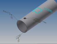
Contour.jpg

Initially, these contours were controlled by surface profile with respect to datums A|B|C. The problem is, we really want the depth of these contours set from the OD surface, because there is a considerable, unavoidable tolerance on the OD of the cylinder, and we're running into CMM issues when inspecting these contours with respect to datum axis A.

Is a directly toleranced dimension on depth unavoidable? if so, how would I go about controlling the other parameters of the contour? I'm not sure the overall perimeter meets the definition of a FOS (at least, not radially), and I know the groove cross section isn't a FOS, so my gut feels that using positional tolerance seems iffy. Im curious to know how others would approach this.
 
Replies continue below

Recommended for you

Is that a depth from the extrapolated circular shape or from going across the sharpish corners of the groove?

Is that the extrapolation from the overall length of the cylindrical surface or on an infinitesimal width of an extrapolated line element on the cylindrical surface and how is that line oriented or is it from an extrapolation from a finite length along the cylindrical surface?

Similarly, if across the sharpish corners, is that from some amount of the groove, or some infinitesimal part of the groove or along a specified finite length along the groove?

How are these measurements affected when moving from a portion of the groove that is radial to one that is axial?
 
The profile of surface 2 to A | B | C does not make any sense. You can't use it unless the groove is dimensioned to coordinate system of datum feature A, B, and C.

Imagine you machine this groove on a 4-spindle machine with a ball end mill, the tip of your ball end mill may not even touch some area of the OD.

By the way, I disagree on calling out both depth and profile of surface. They would be over-dimensioned.

Best regards,

Alex
 
Last edited:
OK. So a stand alone depth profile (not a general profile) should be applied to the bottom of the opening, right?

Burunduk,
This is what you are saying? Because, if general profile is to be applied, then I think it is not crystal clear.
But if you apply a stand alone profile to the bottom of the opening AND in addition you apply what pmarc reccomended (a direct toleranced dimension) then I think you have a strong argument that BOTH requirements/ specifications shall be meet.

Is my understanding correct?
The OP applied the profile specifically to the groove. Not sure where your concern about a general profile comes from, I don't think pmarc mentioned "general" or UOS, I didn't either...
 
greenimi,
Burunduk nailed it.

Burunduk,
I guess that person might or might not be right depending on the tolerance values used.

In the OP's case, I assume the profile tolerance must be more generous than the tolerance for the groove depth, hence, in my mind, my proposal makes sense. But if the overall tolerance for the depth was to be greater than the depth variation calculated from the stack-up of tolerances (for the OD size and the groove profile), then specifying the depth dimension would not work.

The same story with your sketch. What you currently show makes sense to me, but if the tolerance for the 30 dimension was changed to, for example, +/-5 then that dimension wouldn't look right.

A side note: There is a figure in the Y14.8 standard for cast, forged, and injection molded parts that shows a sort of similar scenario to yours; a wall of nominal thickness of 4, for which both sides are controlled with a general surface profile tolerance of 0.8 relative to a fully constrained DRF, but there is an additional directly toleranced wall thickness dimension of tolerance +/-0.2 added to that. In my opinion, since the size limits for the wall thickness are within the limits otherwise imposed by the profile tolerances (i.e., +/-0.8), everything holds water.
Thank you for the answer, pmarc.
It is interesting and surprising, but makes a lot of sense at the same time. I think I won't be wrong saying that most people I worked with and who know something about tolerancing, would consider the toleranced overall length (30+/-...) dimension in my sketch almost a blasphemy when combined with the 3 other dimensions. That is regardless of the specified tolerance being smaller, larger, or equal to the accumulated variation of +/-3 (three times +/-1). However, if the tolerance is smaller than +/-3 it does work as a refinemet and non-redundant, so you make a good point there. This is reinforced by the Y14.8 example you brought up.
 
how it is dimensioned is Meaningless if the part cannot be realistic obtained without the proper machined restraints. some how the propher tooling requirements get lost in the deciphering of the specification.
back to basics 101 machining practices and less arguing what is the dimensioning.
I think it is realistic.
If the OD is not too deformed and the variation in size is not too large within a batch (and it doesn't have to use the entire tolerance), a decent machinist can manage the groove depth after scrapping a couple of the first parts (possibly out of a batch of 1000) during set-up time whan small adjudtments in the CNC program can be made.
 
As long as only the depth matters a depth stop can be used on the cutter to ensure it gets the exact depth to the sharpish corners; no need for any scrapping of parts. The motion of the part can be on a rotary axis mounted on a linear axis and the tool pressure applied by a machinist to keep the ideal contact pressure, in the event the CNC cannot monitor thrust loads on the spindle.

None of this handles that the actual groove path is not controlled.
 

Part and Inventory Search

Sponsor