Eng-Tips is the largest engineering community on the Internet

Intelligent Work Forums for Engineering Professionals

Earth mat design Using ETAP software for Industrial substation (High Short current Fault) 4

Status
Not open for further replies.

Saiedsadat

Electrical
Apr 29, 2021
7
0
0
AT
Dear all,

I have a 1.6MW,400V Gas Engine-Generator with Y Generator and i want to connect it to Y side of a Dyn5 (0.4/20KV) transformer to parallel with grid. in Etap when i earth both of generator and transformer solidly , 75KA phase to earth fault detects in downstream Bus. Fault discrimination is about 0.5 sec and soil RHO is about 100.
I've tried to design Earth mat using Etap Software but the result is Surprising.(Surface and the number of rods are very High).
The factory power system is TNS and I don't want use NGR to reduce Neutral Current.

Any Suggestions?

 
 https://files.engineering.com/getfile.aspx?folder=dad9c158-dc6d-4c4c-b4b6-a531846c5183&file=Factory.bmp
Replies continue below

Recommended for you

At the first place I donot know whether your Utility will allow you to synchronize and export power
with the main transformer connection of DELTA/wye(earthed 400V side). So you can have DELTA/wye on the paper
but not in real situation.

If you create a single line to earth fault with your generator WYE(SOLID) earthed and the
step-up transformer low side also solidly earth, it is obvious that you will get a very high earth fault current
(even greater than the 3-ph bolted fault current value) due to two sources paralleled in Thevenin's eqt cct.

So if that current comes to 75kA, I think unless you make the grid in PLATINUM, you will not be able to control
GPR & Transferred potentials.
 
Saiedsadat,

The 75 kA may be correct as fault to metallic circuit, but the current injected to ground cannot be bigger than 0.217/Rground, surely a small fraction of 75 kA.

Regards,


Thanks for replies
0.217/Rground ?
How do you calculate this 0.217/Rground?
Any references?
As I understand I should design earth mat for this value,Correct?
 
Do not need make such calculation in the 400V level with TNS system. Earth current is back via PEN.
You have calculated on the 20kV side only.
 
Saiedsadat,

In low voltage circuit, the current to ground can't be bigger than Uphase/Rground, or Uline/sqrt(3)/Rground.

I assumed that your Uphase was 0.217 kV as the figure you sent, really is is 0.400/sqrt(3)= 231 V.

Rground is the resistance to ground of your grid1 electrode.

The SC current in 20kV side is 500/20/sqrt(3)= 14.43 kA.

The Uphase is 20/sqrt(3)= 11.55 kV

The current to ground can't be bigger than 11.55/Rground

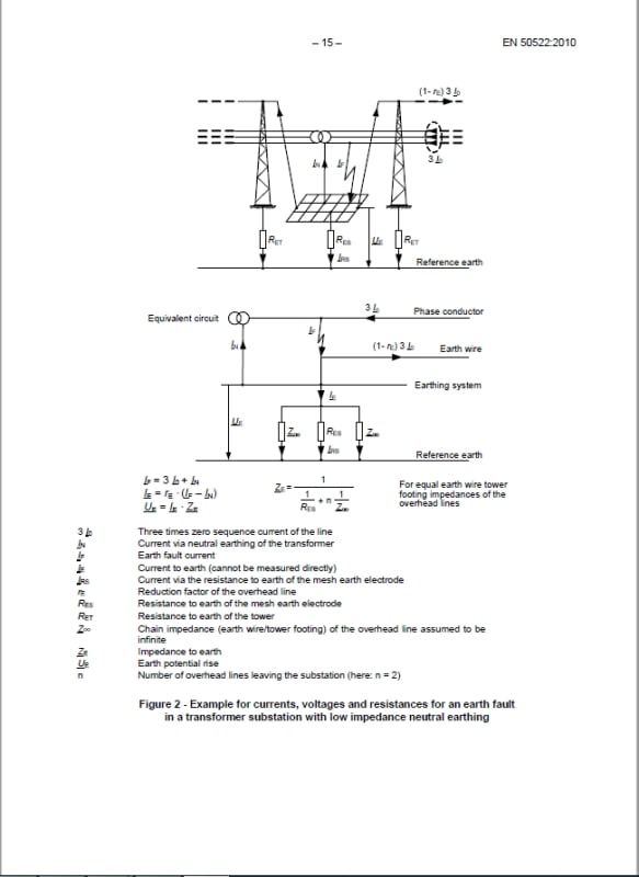
A fraction of the fault current returns to the source by neutrals, the rest is really injected to ground.

The Standards (as VDE and EN50522) explains in the figure the paths of the fault current.

faults_pknlq5.jpg


Regards,

OPH. 2021-05-01 10:06
 
Good explanation of erdep!!!
Saiedsadat, take in account, 400V is solid ground.
important point: EN 50522:2010 Earthing of power installations exceeding 1 kV a.c.
 
One more question.
If there be more than a transformer in site should I consider any probability coefficient for LV side ground fault?
 
Saiedsadat,

I am not sure if the Standards have such probability coefficients.

More transformers, more fault current, but current to ground are no increased, because the bigger fraction of current returns via neutral to the transformers.

In some cases the neutrals of transformers can be disconnected, with only one connected all the time. This is to reduce the fault current by busbars, etc., not the current to ground.
At least, it was the practice in Argentina in the local power company were I worked. I am retired since 1996, I suspect nothing was changed.

Regards,

OPH. 2021-05-01 11:35


Status
Not open for further replies.
Back
Top