Continue to Site

Eng-Tips is the largest engineering community on the Internet

Intelligent Work Forums for Engineering Professionals

  • Congratulations MintJulep on being selected by the Eng-Tips community for having the most helpful posts in the forums last week. Way to Go!

Earth pressure to resist overturning in shallow footings

Status
Not open for further replies.

BW_Engineer

Civil/Environmental
May 18, 2022
9
thread507-367772
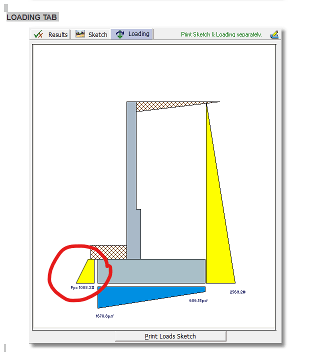
I have a client wanting a design for a shallow precast sign foundation. A prior engineer on the project utilized soil pressure (from the backfill) to resist sliding and overturning from wind, seismic, and impact. This is contrary to what I know is correct (for overturning at least). In my search for answers to justify this approach I came across the above referenced thread which bolstered my position. I also came across the white paper from Bently (link below) that details how to use their software to utilize the soil pressure for just this purpose.


Granted with the software you can opt to use or not use the soil pressure but why even have it as an option for spread footings? Is there any code I can reference for my client that expressly prohibits or discourages the use of soil pressure to resist overturning?

Thanks in advance for your thoughts/comments....first time commenting on the site but have followed many conversations and gleaned a lot of information over the years.
 
Replies continue below

Recommended for you

yes...i'm in CA but registered in CA and FL. The design is somewhat generic in nature and is intended to be applied in multiple areas....am looking at worst case scenarios. The wind seems to be the controlling factor. Seismic force is high but the moment created by it is similar to thw wind moment and both are extreme category events so won't ever be combined.

Thanks for all of the input.
 
Not to fixate on the terminology here, but passive pressure is lateral, (active and at-rest as well) as I recall. What it sounds like you are describing and proposing to use is soil overburden. Unless I misunderstand it sounded like you were wanting to use the weight of the soil above the foundation.
 
Enercalc uses passive pressure to resist overturning in their retaining wall module. Although if you use that you should probably reduce it by the active pressure.


enercalc_passive_s9ynqm.png


[URL unfurl="true"]https://media.enercalc.com/sel_help/index.html?cantilevered_retaining_wall.htm[/url]

They also have an option to use the 'vertical component of active pressure' to help resist sliding and overturning. This is definitely more liberal than the passive pressure on the toe.

enercalc_vert_comp_fwts7x.png
 
BW - Based on a couple of your responses it sounds like you want a one-size fits all approach which always sounds great in the beginning but rarely works. In the 300 MRI wind speed map which is same as ASCE 7-16, Fig 26.5-1A for Risk Category I "other" structures, using 150 mph will certainly get you there. However, for 85% of the US the wind speed is 105 mph and SQRT(150^2/105^2) = 2.0x the wind pressure of the 150 mph isobar in Florida. For the west coast where V = 85 mph that equates to SQRT(150^2/85^2) 3.1x your FL wind pressure. If you look at the isobars 85-105 mph you cover at least 85% of the continental US. 105-150 mph is about 10% leaving 5% > 150 mph. You are grossly over-designing the footing size for the majority of the US, so your one-size fits all approach is more costly for 85% of the US. Not sure if this helps but in the far back of ACSE 7 in the commentary to Appendix C (Appendix CC)are wind speeds for 10, 25, 50 and 100-yr MRIs. Its been a long time since I've designed to AASHTO standards so not sure if you need the 100-yr or 300-yr MRI wind speeds.

Not sure how you got 125 psf wind pressure for 150 mph. For your one-size fits all approach you would have to assume the worst case and use §26.7.2 Surface Roughness 'D' and §26.7.3 Exposure Category 'D' for coastal areas or mud flats in open areas resulting in Velocity Pressure Coef. Kz = 1.03 in Table 26.10-1 for 0-15' average height height and Kd = 0.85 resulting in a wind pressure qz = 50 psf (LRFD) x0.6 = 30 psf (ASD). A sign is an "Other" structure falling into ASCE 7, Chapter 29 then assuming Cf = 1.80 from ASCE 7 Fig 29.3-1 which varies depending on your aspect ratios and opening below the sign and G = 0.85 you should be in the range of applied wind pressure p = 30 psf x0.85 x1.80 = 46 psf (ASD) for your applied wind pressure on the sign when determining bearing pressures and sliding forces. Similar to above, the majority of your locations are going fall into Wind Exposure Category 'C' due to local terrain. Changing to Kz = 0.85 (Exp 'C' h = 0-15') results in wind pressure qz = 42 psf (LRFD) x0.6 = 25 psf (ASD). The applied load on the sign comes from multiplying by GCf and p = 25 psf x0.85 x1.80 = 38 psf (ASD). F = 38 psf x3.0' x8.0' = 912 lbs→ (ASD) lateral load.

This assumes AASHTO follows the same basic wind equations as ASCE 7.
 
Whenever I include ACTIVE pressure in the overturning loads, I will almost always use passive pressure resistance of the soil. Unless there may be no soil on that side or there is no compaction requirements for the back fill.

For sliding, my old boss (he must be VERY old now) encouraged us to use 100% of the larger of passive pressure or friction, and add that to 50% of the smaller value. That was rarely needed thought. And, I don't recall whether we did that for overturning. I would feel comfortable with that concept (50% of passive pressure force), even for spread footings.... Especially if I know they're going to compact the back fill or there is going to be a reasonably rigid asphalt (or concrete) finish poured right up to the pedestal.
 
Thanks ZiggyKS....I think the AASTHO LTS is based on ASCE 7 but I was not aware of the 10, 25, 50, and 100yr MRI tables. This will be helpful in the analysis. Thanks for pointing these out.

You are correct on the design approach as well....it's kind of a one (or two or three) size fits all approach. The florida/gulf coast area would have one design and the rest of the country could use the other design. Your review of the wind maps helped me see it more clearly though so thanks again for that. AASHTO only has 300, 700, and 1,700MRI values with 300 being the lowest risk category. I will have to review in more detail to see if I can justify dropping to a lower MRI windspeed value.

Re: pressure on the sign. The Wind Pressure Pz = 0.00256KzKdGV^2Cd.
As you illustrated, the wind velocity has the greatest effect on the pressure since it is the only variable in the equation that is squared. I had 180mph plugged into my spreadsheet and that's how I got the 125psf. With the windspeed at 150mph this drops to 86.55psf. I'm using a Kz(height and exposure factor) of 0.74 which is calculated per equation 3.8.4-1 and a Kd(directionality factor) of 0.90 which is from an AASHTO table. Cd(drag coefficient)is a table/calculation and comes in at 1.98 for a square sign with the given dimensions. AASHTO also requires G(Gust Effect Factor) to be 1.14 (Section 3.8.6). I think prior versions allowed some flexibility for this value but now it is fixed at 1.14.

Using ASCE7 will allow more flexibility but I like the security of pointing to the prescriptive design of AASHTO.....it's looking very conservative though.

 
I like this approach JoshPlumSE. I'll run some numbers using this approach and see where the design lands.
 
I think AASHTO and ASCE are divergent when it comes to the gust effect factor. ASCE allows the 0.85 for a rigid structure. AASHTO considers everything a wind sensitive structure and defaults to the 1.14 G value. So instead of decreasing the force by 15% the value is increasing by 14%. Not as significant as the windspeed determination but significant.
 
AASHTO only has 300, 700, and 1,700MRI values with 300 being the lowest risk category. I will have to review in more detail to see if I can justify dropping to a lower MRI windspeed value.

Actually, AASHTO includes the 10 year MRI map, also.

Anyway, the most economical spread footing option would be rectangular instead of square, since the wind force on the sign face would be much larger than the force from the side.

Of course, an augered hole with a wood pole, or a steel pole in or on a drilled shaft/caisson is far more economical in most locations where it's feasible to drill a hole.
 
Status
Not open for further replies.

Part and Inventory Search

Sponsor