Eng-Tips is the largest engineering community on the Internet

Intelligent Work Forums for Engineering Professionals

Earth Resistance Testing by Loop Method vs. Earth Ground Clamp 2

Status
Not open for further replies.

Carlos Melim

Electrical
May 31, 2018
24
0
1
PT
Good morning everybody,

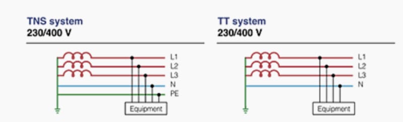
I want to measure the earth-resistance on a primary substation with separate N and PE grounds.

I have measured it with 3-wire connection earth resistance loop test on the LV panel. I am using a FLUKE 1653B tester. The result was over 40 Ohm.

I have also connected the two grounds and, around the connecting wire, I have used an earth ground Clamp. The result as around 5 Ohm. I didn´t

cut off the power to perform the earth ground clamp test.

Any explanation to the different results? I´ve suspected there was a problem with the substation transformer, maybe on the offload voltage tap changer. Some type of rust that could justify the high earth resistance loop test result.

I have inspected the transformer thoroughly and it was all fine.

I am not very familiar with earth ground Clamps. Am I doing something wrong?

I am looking forward to hearing from you. Any help will be greatly appreciated.

Best regards.

Carlos Melim
 
Replies continue below

Recommended for you

Carlos,
It looks like you are from the IEC world and trying to test a LV installation.
You are trying to measure,
1) Earth fault loop resistance (Zs)
2) Earth electrode resistance (RE)
per BS7671 (IEE wiring regulations-17th ed)

The method of testing depends on the earthing method of your
LV installation. Is it TT or TN (TNC/TNCS)?
 
Hello Kiribanda

I want to measure the earth electrode resistance RE.

The installation is TT so it has two different grounds: neutral and PE. With the earth ground clamp, I connect both with a temporary jumper and measure the sum of the two grounds. I get 5 ohm and I’m happy with it. I make the measurement without disconnecting power or cables.

Then I perform an earth loop measurement, 3-wire, with my FLUKE 1653B. I get a RE result of 47 ohm.

Surely I’m failing at something.

Any suggestions?

Thanks for your help.
 
The clamp type instruments relies on a return path for the test current via a path significantly lower in impedance than the electrode under test. The measurements are unreliable when used with isolated earth electrodes, e.g. single rods. They do have value where multiple rods interconnected rods form a large array.

If you want a proper measurement on an isolated electrode then use a fall of potential set, something like a Megger DET-2.
 
Hello ScottyUK.

I know that clamp type instruments work better if there are several electrodes in parallel with the one I want to measure. I’m really just paralleling the PE and neutral electrodes through a temporary jumper. But I would expect the measured resistance to be higher that the real one.

My main doubt is the different results I get from the earth ground clamp and the earth loop measurement test. If there is a problem with the neutral electrode (that I suspect to be the case) it should shown on both measurements. The clamp measurement should be even higher than the earth loop one. Isn’t that so?

I will try to perform a fall of potential test in spite of the lack of garden areas close to the primary substation. If I get, for the neutral and PE electrodes, high values similar to the earth loop measurement, I will be suspicious of the clamp method feasibility.

Thanks for your help.


Carlos Melim said:
The installation is TT so it has two different grounds: neutral and PE. With the earth ground clamp

If it’s TT there isn’t a PE.
My understanding is you’ve described a TNS
Maybe it’s my misunderstanding
8B8D3CDE-49B8-4066-97AF-F04DA42C3EA3_gnlr7l.jpg
 
Hello Palletjack

I am dealing with TT system. TT, TN-S and IT, all have PE.

SLT_ua3up0.png


TT has different earth electrodes for the neutral (RB) and for protective earth (RA).

Connecting RA and RB with a temporary jumper and applying an earth ground clamp the result is RA+RB.

If the value obtained is less than 20 ohm, then both electrodes resistance is smaller than 20 ohm and the installation is safe.

As I´ve described in the previous posts, I get 5 ohm reading with an earth clamp but 47 with an earth loop measurement test device.

That´s what puzzles me.

Fell free to add any comments.

Thanks.
 
Is the source a local transformer or a multigrounded utility system? If it is local transformer, the earth ground clamp in not appropriate because there are no paralleled grounds on the source side of the clamp. If it is a multigrounded utility system, then you can use the earth ground clamp, but what you are measuring is the resistance to remote earth of RA and RB in parallel. What you are measuring with the earth loop measurement is the resistance of the connecting wires, not the resistance to remote earth RA or RB.
 
I donot think you are doing the test correctly. In a TT system you cannot bridge the PE & N and take a measurement for the electrode.
It will indicate some reading but for me it is wrong.

You have to electrically isolate the electrode and measure its resistance (RE) using the fall of potential method.
FLUKE 1653B describes how to do it in Fig. 20.

In a TT system,
1)if you are using RCCBs for earth leakage protection,then you have to satisfy the condition
I(RCCB)x RA = 50V which is the safe touch voltage for IEC & BS. Now you should know that,
RA=RE (resistance of the electrode) + PE (resistance of the protective conductor).
Then, you are allowed to have RA = 1666 Ohms as the maximum allowable. But a value exceeding 100 Ohms for the electrode RE is not acceptable.

2)If you are using mccbs/mcbs for your earth leakage protection,then you have to satisfy the condition
ZS x I (mccb/mcb) = Phase to ground voltage. Then you have to measure earth fault loop impedance (ZS)
using FLUKE 1653B verify whether the above mentioned condition is met.
 
Status
Not open for further replies.
Back
Top