Hi!
I am trying to find an easy and conservative method to calculate fillet welds while using the results of FEM software structural utilization of members. I was interested to know if this method could be acceptable, and if you have other ideas to facilitate weld calculation:
Plate:
Linear Resistance to Compression in a Plate: crpl = 0.9 * Fy * tpl (Unit of Force / Unit of Plate Length)
Linear Resistance to Shear in a Plate: vrpl = 0.9 * 0.6 * Fy * tpl (Unit of Force / Unit of Plate Length)
Max Linear Resistance in a Plate : rplmax = 0.9 * Fy * tpl (Unit of Force / Unit of Plate Length)
Weld:
Linear Resistance to Shear in a Fillet Weld (Weld) : fw1 = (0.67 * 0.67 * Xu) * (dw / sqrt(2)) (Unit of Force / (Unit of Weld Length))
Linear Resistance to Shear in a Fillet Weld (Base Metal): fw2 = (0.67 * 0.67 * Fu) * (dw) (Unit of Force / (Unit of Weld Length))
For Fu = 450 MPa and Xu = 490 MPa:
Min Linear Resistance in a Weld: fwmin = (0.67 * 0.67 * Fu) * (dw / sqrt(2)) (Unit of Force / (Unit of Weld Length))
Where:
dw = Weld Leg Size
tpl = Plate Thickness
Fy = Yield Stress
Fu = Ultimate Tension Stress
If we want to find the fillet weld size required so that the weld is as strong as a given plate thickness, for Fy = 300 MPa and Xu = 490 MPa, would it be conservative to affirm that:
rplmax = fwmin
0.9 * Fy * tpl = (0.67 * 0.67 * Fu) * (dw / sqrt(2))
dw = sqrt(2) * (0.9 * Fy * tpl) / (0.67 * 0.67 * Fu)
dw = 2.835 * (Fy / Fu) * tpl
dw = 2.835 * (300 MPa / 450 MPa) * tpl
dw = = 1.89 * tpl
Say you have a plate of 6.35 mm of thickness, then it would require a weld size of this size to be as resistant as the plate:
dw = 1.89 * 6.35 mm = 12 mm
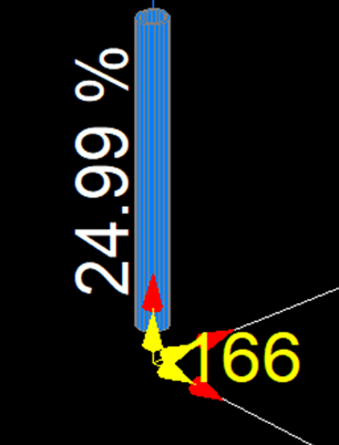
Now, if you use your FEM software that's used to calculate the structural utilization in a member, and find that a member near a connection is utilized at 24.99 %, the weld is all around a round HSS member (tpl = 6.35 mm), would you say it would be conservative to put a weld of this size:
dw = 2.835 * (Fy / Fu) * tpl * Utilization
dw = 2.835 * (300 MPa / 450 MPa) * 6.35 mm * 24.99 % = 2.99 mm

CSA S16 and CSA W59 were used in this calculation.
I am trying to find an easy and conservative method to calculate fillet welds while using the results of FEM software structural utilization of members. I was interested to know if this method could be acceptable, and if you have other ideas to facilitate weld calculation:
Plate:
Linear Resistance to Compression in a Plate: crpl = 0.9 * Fy * tpl (Unit of Force / Unit of Plate Length)
Linear Resistance to Shear in a Plate: vrpl = 0.9 * 0.6 * Fy * tpl (Unit of Force / Unit of Plate Length)
Max Linear Resistance in a Plate : rplmax = 0.9 * Fy * tpl (Unit of Force / Unit of Plate Length)
Weld:
Linear Resistance to Shear in a Fillet Weld (Weld) : fw1 = (0.67 * 0.67 * Xu) * (dw / sqrt(2)) (Unit of Force / (Unit of Weld Length))
Linear Resistance to Shear in a Fillet Weld (Base Metal): fw2 = (0.67 * 0.67 * Fu) * (dw) (Unit of Force / (Unit of Weld Length))
For Fu = 450 MPa and Xu = 490 MPa:
Min Linear Resistance in a Weld: fwmin = (0.67 * 0.67 * Fu) * (dw / sqrt(2)) (Unit of Force / (Unit of Weld Length))
Where:
dw = Weld Leg Size
tpl = Plate Thickness
Fy = Yield Stress
Fu = Ultimate Tension Stress
If we want to find the fillet weld size required so that the weld is as strong as a given plate thickness, for Fy = 300 MPa and Xu = 490 MPa, would it be conservative to affirm that:
rplmax = fwmin
0.9 * Fy * tpl = (0.67 * 0.67 * Fu) * (dw / sqrt(2))
dw = sqrt(2) * (0.9 * Fy * tpl) / (0.67 * 0.67 * Fu)
dw = 2.835 * (Fy / Fu) * tpl
dw = 2.835 * (300 MPa / 450 MPa) * tpl
dw = = 1.89 * tpl
Say you have a plate of 6.35 mm of thickness, then it would require a weld size of this size to be as resistant as the plate:
dw = 1.89 * 6.35 mm = 12 mm
Now, if you use your FEM software that's used to calculate the structural utilization in a member, and find that a member near a connection is utilized at 24.99 %, the weld is all around a round HSS member (tpl = 6.35 mm), would you say it would be conservative to put a weld of this size:
dw = 2.835 * (Fy / Fu) * tpl * Utilization
dw = 2.835 * (300 MPa / 450 MPa) * 6.35 mm * 24.99 % = 2.99 mm

CSA S16 and CSA W59 were used in this calculation.
