Continue to Site

Eng-Tips is the largest engineering community on the Internet

Intelligent Work Forums for Engineering Professionals

  • Congratulations pierreick on being selected by the Eng-Tips community for having the most helpful posts in the forums last week. Way to Go!

eccentric floor truss connection

struct_eeyore

Structural
Feb 21, 2017
263
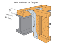
I'm sure many of you who work in residential see this type of connection often.
The other variation is where the web is packed out with 2x and the joist/floor truss bucket is attached to it.

My question: When trusses come in to one side only, the torsion can get pretty high, especially on wide(r) flange beams. When I'm dealing with approximately equal spans, I usually don't sweat it. Now I have a condition where I have both, a large span, from one side only, and a doubly packed web. I opted out of dropping the beam, and bearing the floor joists over the full flange to kick the load directly into the web. But, I'm curious if any of you have some other means to justify a single sided connection with joist and beams in plane. Thanks
 

Attachments

  • wood-steel-connection.png
    wood-steel-connection.png
    251.1 KB · Views: 6
Replies continue below

Recommended for you

Is the beam not fully restrained by the floor diaphragm? Is your bolt spacing through the nailer sufficient to restrain, and is there sufficient nailing to the floor sheathing to resolve the torsional loading?
 
@Choras,

In case of a simple hanging top-flange-bucket (same as shown), floor sheathing wouldn't really provide any torsional restraint.
With a face nailer, you end up relying on nail withdrawal to resolve your couple, which would likely not be sufficient for many pre-engineered buckets.
 
I don't agree, the floor sheathing will restrain the nailer plate, which is directly connected to the steel beam. Alternatively, when we start getting into significant lateral torsional buckling deflections, any deflection in the top flange of the steel beam will then load axially into the joist system, which is then directly restrained by the diaphragm, unless the framer missed every nail.

Recall that no member is truly straight or perfectly aligned during framing, so Euler's buckling load is an accurate mathematical model, but not representative of reality, because the members are not perfectly pin-pin at ends, the member is not perfectly straight or uniform in properties, etc. So as we approach the Euler buckling limit, deflection occurs (generally called P-delta in ASCE), until we hit the buckling load and observe significant displacement. The p-delta effects are what I describe above, where even if the nailer does not restrain the w section, the joists will be engaged directly through axial load due to deflection of the top of the member, even slight deflection would engage and redistribute the LTB load.
 
For facemount connection with a wood web filler, you are not inducing any meaningful eccentricity, as you are loading the steel beam web directly. Unless you are assuming the wood filler block is directly loading the bottom flange at some bearing distance, d, away from edge of flange? In that case, I would suggest bolting to the web directly and leave an air gap below the filler, to prevent the eccentric loading.
 
For a top flange hanger connection, it is def. a concern as I have seen beams rotate in the field. Never seen it in flush beam connections but I am pretty careful about not getting into situations where the load is heavily unbalanced.
 
Last edited:
@Choras - this is not about LTB, but rather direct torsion on a beam loaded on a single side only. A couple is needed somewhere to resolve, which with top flange hangers can only occur at the supports - i.e. the skinny shear tab which are good for nothing. With packed out beam and a gap, you'd still be relying on a couple formed by the top and bottom nails in the bucket to create enough continuity to carry the shear directly to the beam web.

@XR - Agree - we never really see full design loads, so I suspect the connectors from buckets on the flush beam connections do indeed provide some retraint - enough to work.
 
I wonder if it would be possible to bolt a wood late to the bottom flange of the steel beam, then brace it to the bottom of the floor truss or I-joist. Guess it depends on the depth of the beam relative to the floor members.
 
In this example I think you're right - there is an eccentric moment, and the top-hung system provides minimal way to resolve it
The beam probably ends up twisting to accommodate and this should be factored into deflection & ultimate moment demand calculations
 
For steel beams in residential I almost never check torsion. If this was a wood beam different story; torsion should always be avoided. If I had a really large point load or something like that I may check it further. But with joists right up against it and a wood subfloor, the chances of it rotating are small.

If I have minimal or no diaphragm, I will run it completely unbraced. That upsize is usually enough to cover any unbalanced loading IMO.
 
I wonder if it would be possible to bolt a wood late to the bottom flange of the steel beam, then brace it to the bottom of the floor truss or I-joist. Guess it depends on the depth of the beam relative to the floor members.
This is where my head was going. I feel like a coil strap from the bottom of the beam flange+nailer to the bottom chord of the truss should take care of this. As usual - somewhat janky.
 
For a top flange hanger connection, it is def. a concern as I have seen beams rotate in the field. Never seen it in flush beam connections but I am pretty careful about not getting into situations where the load is heavily unbalanced.
Perimeter deck girders come to mind with this topic. Most always unbalanced load, and face mount connections a lot of the times. Spans aren't usually very long but I've often wondered why these don't "roll".
 
Perimeter deck girders come to mind with this topic. Most always unbalanced load, and face mount connections a lot of the times. Spans aren't usually very long but I've often wondered why these don't "roll".
As struct-eeyore stated, the flush hangers (or ledger and toenails) seem to have enough restraint. I mean this is a pretty standard connection used EVERYWHERE in light frame construction and has excellent reliability. If it is over 2 members thick, I start adding straps though to mitigate the torsion.
 
Interesting one - I just built a sample model to play round with this
Assuming a 7m beam span supporting 4m floor joists on one side @ 400 crs
Apply a realistic 0.6kPa loading to simulate dead load + nominal furniture etc
Assume the loading is at ~80mm from the beam web (I modelled a 310UB40 so this is approx half the beam width)
0.6kPa * 0.4m crs * 4m span / 2 = 0.48kN/end
0.48kN * 0.08m = 0.0384kN.m/m -> I applied 0.04kN.m/m for simplicity

Modelling the 310UB and subdividing it at ~400crs with 2m long stubs sticking sideways shows the max deflection at the end of the stub as ~39mm
This is a fudge obviously but it gives some estimate of how much roll is in the UB and what impact that has as a rigid body deflection
The load at the supports is only ~0.14kN.m torsion so it's not much at all to take out - a standard cleat into double stud would easily transfer this out through two bolts
Now, we aren't (I hope) seeing beams rolling their joists to 40mm deflections in reality so there must be sufficient strength in the connector to handle this moment and put it back into the joists
 

Part and Inventory Search

Sponsor