ak.t
Structural
- Dec 18, 2019
- 73
Hi All,
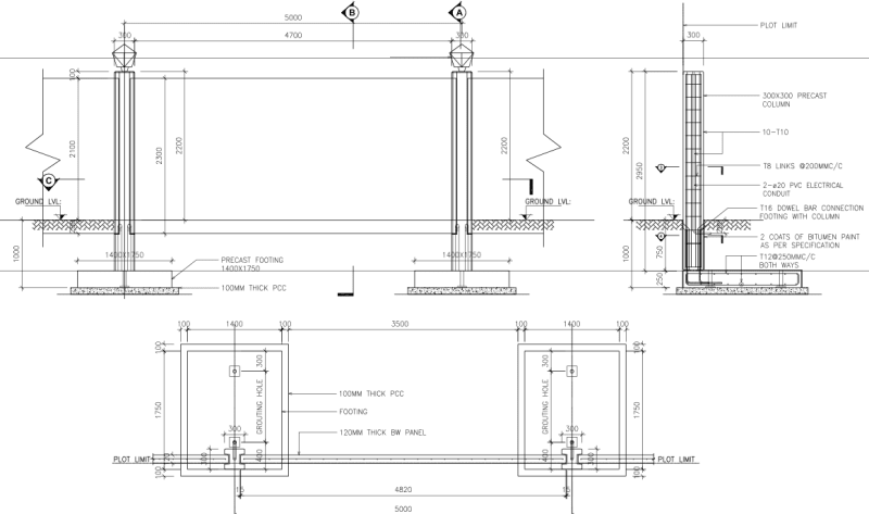
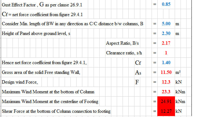
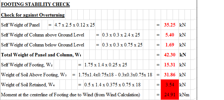
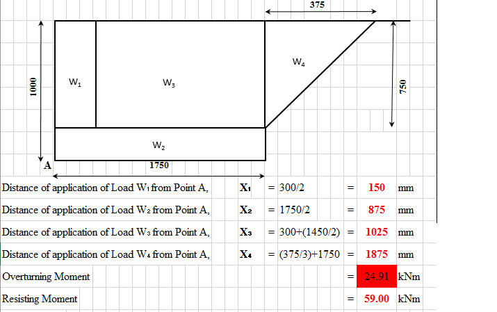
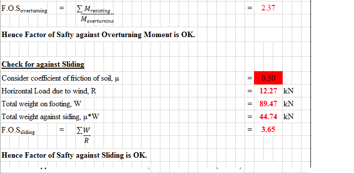
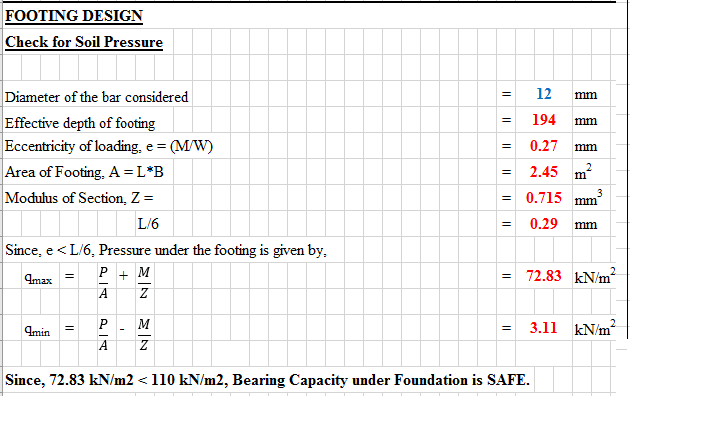
The footing size is (1.4 x 1.75)m (Fig. attached) & the SBC is 110 kN/m2
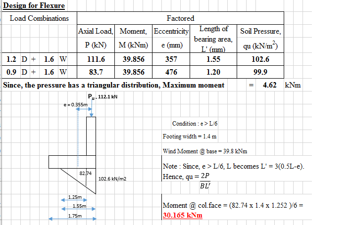
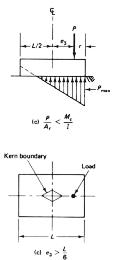
I get e> L/6 condition, Hence, I applied the 2P/BL' to calculate pressure max;
where L' is the bearing length = 3* (0.5L-e)
Thus, Qu = 2P/BL' = 102.6 kNm2
L' = 1.55 m ; P = 111.6 kN(Factored, Calculated) ;
M = 39.856 kNm (Factored, Calculated)
L = 1.75 m ; e = 0.357 m
How do I calculate moment for reinforcement from this triangular pressure profile ?
In report i found that Moment is 4.62 kNm. But I could not get the same.
Thank you.
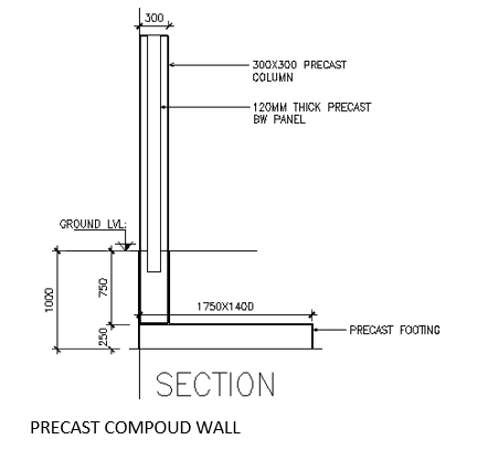
The footing size is (1.4 x 1.75)m (Fig. attached) & the SBC is 110 kN/m2
I get e> L/6 condition, Hence, I applied the 2P/BL' to calculate pressure max;
where L' is the bearing length = 3* (0.5L-e)
Thus, Qu = 2P/BL' = 102.6 kNm2
L' = 1.55 m ; P = 111.6 kN(Factored, Calculated) ;
M = 39.856 kNm (Factored, Calculated)
L = 1.75 m ; e = 0.357 m
How do I calculate moment for reinforcement from this triangular pressure profile ?
In report i found that Moment is 4.62 kNm. But I could not get the same.
Thank you.
")