Eng-Tips is the largest engineering community on the Internet

Intelligent Work Forums for Engineering Professionals

eccentric loading on steel I beam 2

Status
Not open for further replies.

struct_eeyore

Structural
Feb 21, 2017
249
0
0
US
So, I'm apologize ahead of time for resurrecting this topic, but having read thru numerous thread, I'm not sure I've entirely satisfied my curiosity.

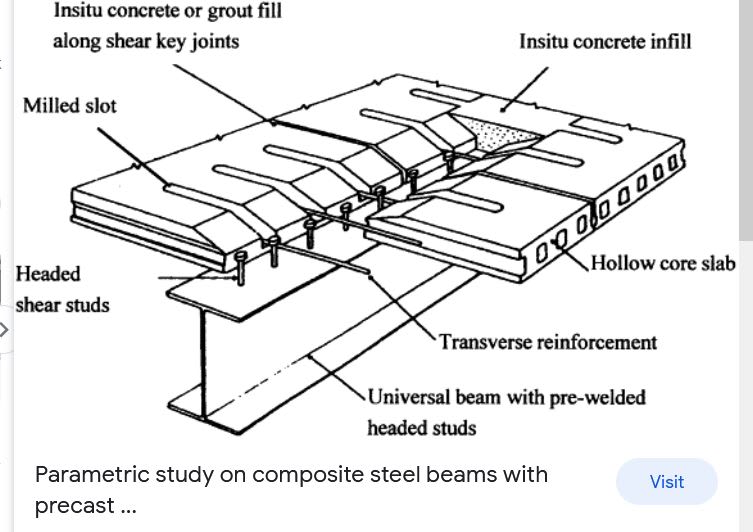
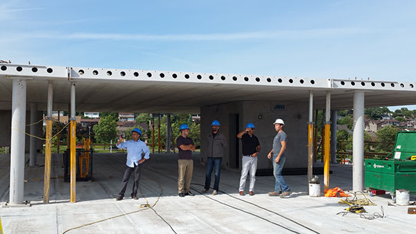
In a very typical scenario where we have hollowcore bearing each side of a wide flange beam, but with eccentric loading - the supposed compatibility torsion condition - where is the actual coupling happening that restrains rotation? Specifically during construction before any topping or reinforcing is in place?

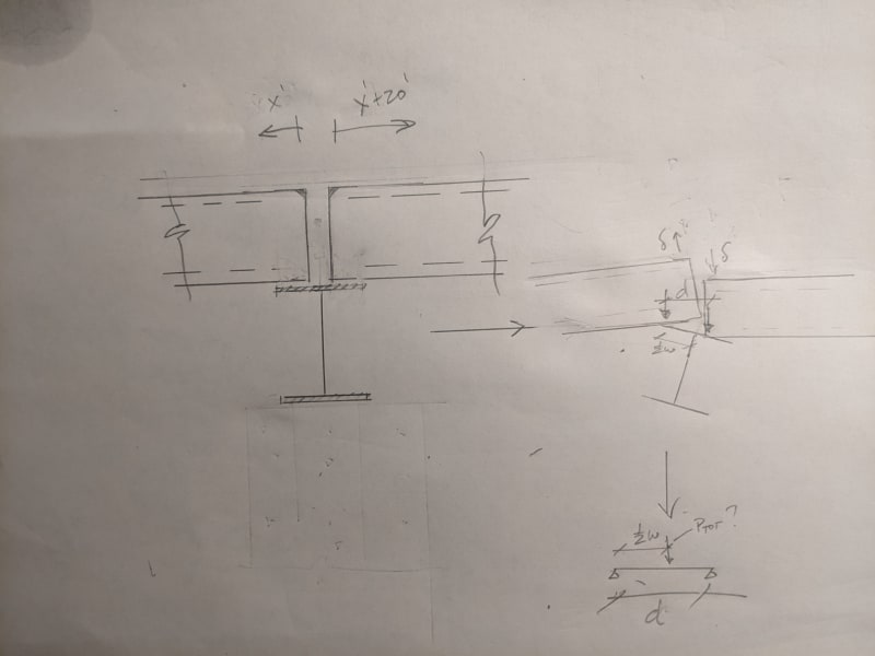
The way I've justified it to myself ( see the sketch below ), is that under exaggerated differential rotation, assuming a fully rigid flange, the bearing(s) will shift until they are just points at tips of the cores. With the lighter section being lifted, and its bearing moving further to the outside, the couple is then restored. In field, I assume this all happens with bearing pressure distributions and minimal rotations at the shear tabs. It then remains to check the flange for yield with the point load acting thru the web - at least as an approximate method.

Any and all input appreciated.

As a followup question - if I bear my beam on an embedded bearing plate each end and weld it down (say with fully developed DBAs into concrete), creating some dregree of torsional restraint - would the warping stresses need additional investigation, or would you not consider it in practice?


PXL_20230928_235630072_jd4agg.jpg
 
Replies continue below

Recommended for you

That is not an acceptable detail. Hollow core slabs should be tied across the steel beam to resist torsion and also to act as a horizontal diaphragm. I believe the usual detail is to leave a gap between the slab ends and use short lengths of reinforcement tying the slabs together. This means filling the cells for about 600mm each slab. If topping is used, it can help provide continuity.
 
For the temporary condition, shoring can be used as required.

Following is one possibility, but there may be easier ways of achieving the same.

Capture_iafeyu.jpg
 
BA - but what is the actual mechanism behind the torsional restraint? The detail above still does not eliminate the imbalanced loads coming in from the planks on either side of the web, it just prevents lateral displacement.
 
It's scary stuff. Sometimes planks will be placed alternately on either side of the beam in sequence to reduce torsion. Sometimes they will shore the longer spanning planks. You can get some torsional restraint out of welded embeds but cranes cannot be made to wait for welders to catch up in realtime.

I agree that the shift in the centroidal locations of the plank reactions as a result of beam rotation is a great benefit. When I've gotten into trouble, it's been with the detail where the planks bear on side mounted ledge angles.

It's uncomfortable to have to place so much trust in the capabilities and diligence of the erection professionals but, in my opinion, that's mostly what makes it work.
 
Koot,

To follow up... Once the planks are in place, say with substantially different spans on either side of beam, there is still no continuity (at least with all the typical details) and the eccentricity persists. And this done all the time (seemingly without question), without any problems (as far as I'm aware) with the shear tabs twisting off. Is any generic LTB restraint really sufficient to eliminate torsional effects? Where does it spill over? In addition to any possible re-distribution of bearing stresses on the flanges (like the model I drew), do the - say headed studs - couple with the tips of the flanges? i.e. the studs in withdrawal and one of the tips of the top flange pressing against the bottom of the planks?
 
structee said:
BA - but what is the actual mechanism behind the torsional restraint? The detail above still does not eliminate the imbalanced loads coming in from the planks on either side of the web, it just prevents lateral displacement.

EDIT: If you are still talking about the temporary condition, I agree this detail does nothing; that would have to be addressed by shoring.

In the permanent condition, I believe that the applied torsional moment would be distributed between slabs on each side of the beam. And if spans are substantially different on each side of the beam, the shorter span would tend to resist the bulk of the torsional moment.
 
structee said:
And this done all the time (seemingly without question), without any problems (as far as I'm aware) with the shear tabs twisting off. Is any generic LTB restraint really sufficient to eliminate torsional effects?

My thoughts on this erection issue (erectile dysfunction?):
a) I think there's a "means and method" issue here associated with construction. Where we can point a contractor in a direction, but we really shouldn't be designing the shorting concepts for them. Unless we were specifically hired us to do so. Otherwise, we take on liability that should be theirs and theirs alone. Right?

b) Because of item 'a', I have to believe that the contractor is experienced with the hollow core construction sequencing. When he needs to make sure there are counter-balancing slabs on either side of the beam and such. When unbalanced spans need to be shored and such. Yes, I may be assuming a lot. But, I don't recall there being lots of erection failures of hollow core slab systems.

c) I haven't actually worked on a building with a hollow core slab. Though I know my previous company had just won a job where this was likely going to be required. So, these are just theoretical ramblings on my part. Partly because I beam torsion issues are an area of interest for me.

d) Were I to really dive into this type of analysis for torsion, I would probably start with the assumption that all the I beams are simply supported on each side and that they have "rotational ductility" sufficient to make this happen. That's the reason why we assume that a wide range of shear only connections can be designed with ONLY shear forces being considered. I'd take a look at the AISC requirements on rotational ductility and see if there were any way I could get this concept to allow for me to ignore torsional moment in the supporting beam (at least during construction). Honestly, I think that's kind of what you were getting at when you talked about looking at the flange bending when a little rotation happens.

e) That being said, I would have a concern for any slab that did not have counter balancing slabs on either side. Say at the perimeter beams of the building. For beams like this I wonder what other people do. Add some stiffeners? Have some transverse moment connected beams tied to the next span (which we always do for slabs that cantilever out significantly past the perimeter columns). Part of me thinks that a channel hat on the beam might help make those perimeter beams better for torsion. Not that expensive, but I don't think I've seen anyone do that sort of thing before.
 
JoshPlum,

With edge beam I think the situation is actually simplified a bit, since we can bring a portion of the hollowcore to bear directly over the web, and which I can only assume will attract just about all the load by being the most rigid bit. And I'm not talking about H/C exclusively, really any slab or floor system that results in a net torque. But rotational ductility I think is the term I was looking for - I have my weekend reading.

EDIT: Internet search comes up barren with references to rotational ductility - what would you suggest?
 
I had this be a problem once, with almost 28 years of experience into my career. I had a one story structure with two equal spans of precast planks. They had embedded plates at their bottoms and were to be welded to the steel beams. I had assumed they would be installed from one end to the other and be welded shortly after being put in place.

Contractor installed all of the planks on one side without any welding. The interior beam was torsionally loaded and failed early the next morning. The exterior beam did not have any torsion and was OK. Fortunately, no one was there when it failed; so no one was hurt.

My design was reviewed and I was not found to be liable. Our plans did not get into “means and methods”, but if the Contractor had the planks welded as they were installed their way, the beam would probably not have failed.

We added intermediate beam(s) on the rebuild to prevent the torsional problems that caused the failure.

gjc
 
Sorry it’s a bit of an optical illusion. You’re seeing a delta beam running left to right, supporting planks that are spanning perpendicular. The shoring props at the ends are for the torsion induced by the planks on one side only. They put the props at the ends because the beams are cambered and need to be able to deflect.

This photo is just interesting to me because without those props, those guys would be standing in a very precarious position. I actually feel like plank collapses during construction is something I hear about with some regularity. The torsion concern is definitely legit, which is why I think delta beam enforces the use of these shoring props with their system. And delta beams being closed shapes are probably an order of magnitude more torsion-resistant than a typical WF beam.

Personally, I like the idea of explicitly designing for the torsion from worst case unbalanced loading, and carrying that through the entire load path. But as I’m sure Koot can attest to, the economics of that approach have probably kept it from being the standard of care for typical plank projects.
 
Status
Not open for further replies.
Back
Top