Eng-Tips is the largest engineering community on the Internet

Intelligent Work Forums for Engineering Professionals

Eccentricity On Walls Transfer to Footings 2

Status
Not open for further replies.

Eng_Girl

Structural
May 12, 2023
19
0
0
CA
Hi all,

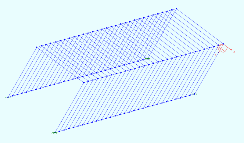
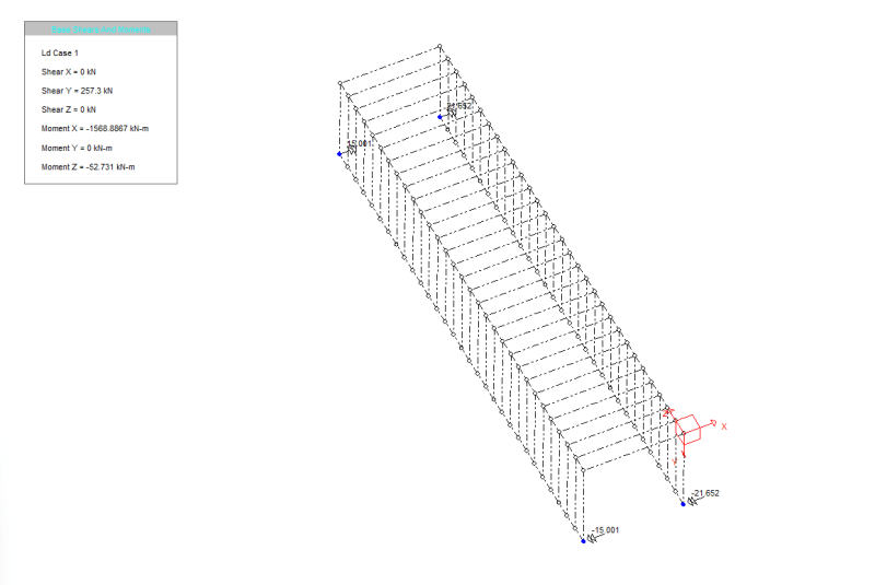
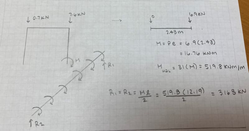
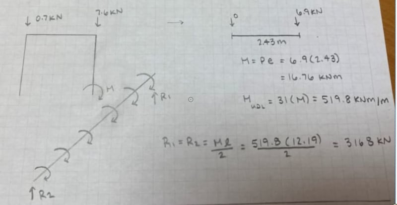
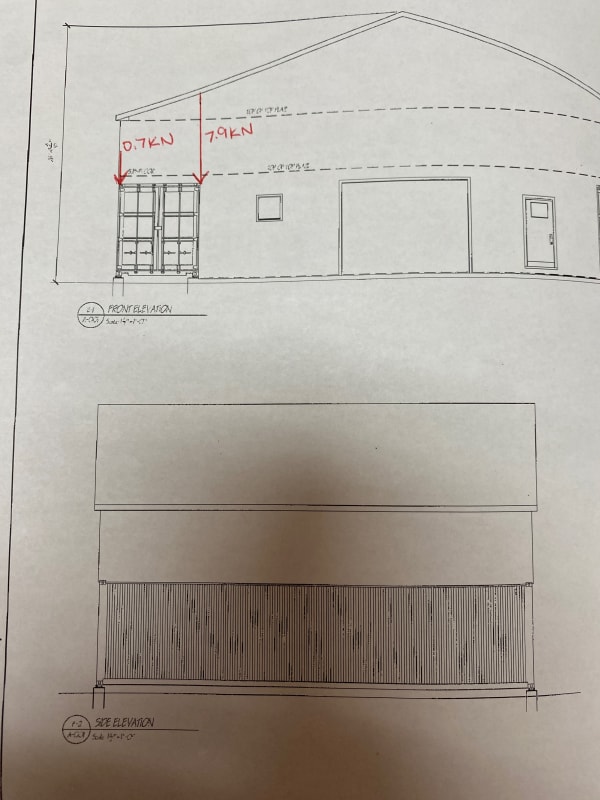
I'm designing a footing for a Secan Building (uses a shipping container for two of the exterior walls). The Secan is supporting the roof load which produces an eccentricity on the container itself, see figure below. The forces in the figure are the reaction of one truss, and due to the design of the container, the entire roof load is supported on four footings (each corner of the container). So there is 31 trusses in total, each imposing an overturning moment to the entire shipping container. How do I transfer the moment to the footing correctly?

huj_znapm4.jpg
 
Replies continue below

Recommended for you

Hi Ryaneng,

Thanks for the reply. Yes I have looked at the loading of the trusses on the walls. I Distributed the reactions from the trusses as a UDL of the walls and checked it for deflection. I then compare to ISO 1496 - 1:1990 (E) which said the allowable deflection was 25 mm (1") and my deflection was 0.02 mm.
 
Allowable wall deflection of 1" axially? Perhaps you're directions are off. What about the stress in the wall? What about local stress beneath the joist?

What is the free body diagram of the footing look like?

FEA models can make these things more difficult than they need to be. But a proper understanding of the load path and a proper set of free body diagrams should answer your question as well as identify other areas of concern.
 
Longitudinal deflection is being specified for longitudinal rigidity testing. I.E. they are pressing on the top of the container, laterally in the long direction (thats how I interpret that).

Perhaps a step back, your not really transferring moment your transferring unbalanced vertical loading. ' The inside wall' of the container takes a much higher vertical force than the outside.
Bigger footings on the inside, okay. Maybe I am missing something but I don't see the same distributed moment here that you have drawn.

The load path from the trusses to the footing is questionable and it needs to be investigated. There is currently some IBC sections in the US that provide capacity of shipping containers, and in future versions there will be more.


Okay, I'll revisit the wall capacity.
And I have designed the footing to take the larger of the two loads, but I didn't want to underestimate the overturning of the container as a whole.
The distributed moment was how I envisioned the global overturning. Maybe I'm over complicating things lol.
 
It seems like you have pad footings. If there was a single mat foundation for one whole container, then the moment makes more sense.

When you have a footing with eccentric load it is ideal to try to keep the pressure as close to uniform as possible because over time an unbalanaced footing becomes more unabalanced due to settlement. (it settles more on the high pressure side)

But when you have pad footings like that you just need to make sure you design them for enough axial load, and you can just size them on each side to have about the same bearing pressure to avoid the problem.

 
I've looked and looked for resources on shipping container standards and using them for structures and cant find any. Do you have some resources that you pull from??
 
Status
Not open for further replies.
Back
Top