MoStructEng
Structural
Hi
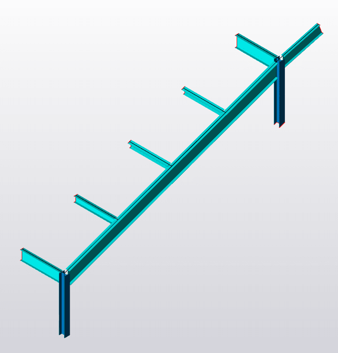
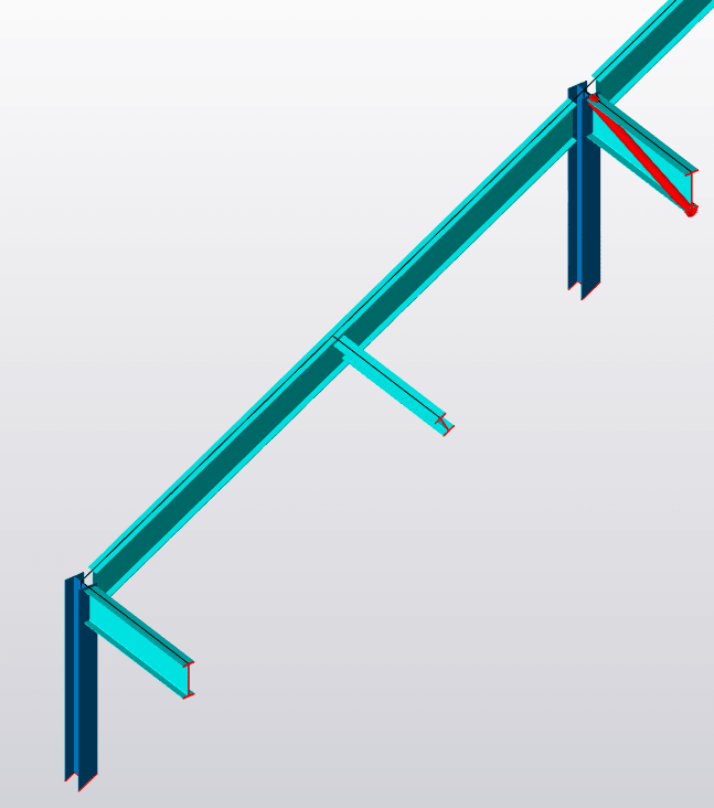
A graduate here. I am using Tekla to design a steel frame to Eurocodes and I've got edge beams with balustrades I did a bit of research and the max allowed deflection for balustrades is 25mm which is about 1.3 degrees only. When I try to limit my torsion and torsional rotation the section that work are astronomical in size, also note that I've got intermediate beams coming in as shown in pic attached that are simply supported to the beam so I assume these provide some sort of restraint. I think that when Tekla does the analysis these incoming beams are not considered to provide restraint. Is there another way for me to check the Balustrades effect on the beam ? Should I model the beam as simply supported with a span equal to the distance between the incoming beams rather than the entire beam length? How do you design beams with balustrades? Any help would be appreciated

A graduate here. I am using Tekla to design a steel frame to Eurocodes and I've got edge beams with balustrades I did a bit of research and the max allowed deflection for balustrades is 25mm which is about 1.3 degrees only. When I try to limit my torsion and torsional rotation the section that work are astronomical in size, also note that I've got intermediate beams coming in as shown in pic attached that are simply supported to the beam so I assume these provide some sort of restraint. I think that when Tekla does the analysis these incoming beams are not considered to provide restraint. Is there another way for me to check the Balustrades effect on the beam ? Should I model the beam as simply supported with a span equal to the distance between the incoming beams rather than the entire beam length? How do you design beams with balustrades? Any help would be appreciated


