Eng-Tips is the largest engineering community on the Internet

Intelligent Work Forums for Engineering Professionals

Effective Length Factor for Double Angles Bolted to Gusset Plate

Status
Not open for further replies.

MegaStructures

Structural
Sep 26, 2019
366
0
0
US
Hello,

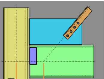
I am trying to determine if it's possible to use an effective length factor less than 1.0 for a double angle bolted to a 1/4" gusset plate. The gusset plate is welded on both sides to a column and a beam. I feel that the length of the member should be measured from center of bolts to center of bolts and the effective length factor should be based on the rotational stiffness of the gusset plate.

First, I want people's thoughts on this approach and if it seems reasonable or unreasonable. Second, I'm looking for a reference that covers this topic (research paper or otherwise) that recommends an effective length factor based on empirical data.

Temp_RISA_dkrduu.png


“The most successful people in life are the ones who ask questions. They’re always learning. They’re always growing. They’re always pushing.” Robert Kiyosaki
 
Replies continue below

Recommended for you

I think you could safely use the distance centre to centre of the last bolts; there would be a slight moment resistance to reduce the effective length beyond that. I don't do that, I generally use the distance between the frame's centrelines. Bracing, columns and cantilevers, I'm generally conservative.

-----*****-----
So strange to see the singularity approaching while the entire planet is rapidly turning into a hellscape. -John Coates

-Dik
 
Thanks Dik. Do you mean the last bolts as in the ones closest to the column, or farthest away?

“The most successful people in life are the ones who ask questions. They’re always learning. They’re always growing. They’re always pushing.” Robert Kiyosaki
 
thanks, Koot...

-----*****-----
So strange to see the singularity approaching while the entire planet is rapidly turning into a hellscape. -John Coates

-Dik
 
Koot, dik,

First, I do not disagree. But I am interested in why you believe it is acceptable to reduce the length of the member by the length of the connection. Do you simply feel that the brace-gusset connection is sufficiently stiff to prevent rotation and translation, up until the last bolt, where the gusset plate then only provides lateral stability and allows the brace to rotate freely?

It seems to me that if you thought this then you would treat the member as fixed-fixed and would account for the reduction in length by using an effective length factor of less than 1.0 rather than picking a point along the member to consider the member overall length.

“The most successful people in life are the ones who ask questions. They’re always learning. They’re always growing. They’re always pushing.” Robert Kiyosaki
 
I would never consider it as fixed-fixed; I would, however, consider it as pinned and pinned at the last bolt. Unless the gusset is long and flimsy, that contributes to the unsupported length... The gusset is likely more rigid than the bracing angle. With any clamping of the last bolt, there will be a degree of fixity and the KL value will be slightly less than 1, I suspect. If it's a wobble braced end, then the centreline of the beams and columns is generally conservative. If you have two bolts at each end, there is likely a fair degree of fixity. I often check Whitmore width for designing gussets just to make sure the gusset doesn't buckle (in my SMath programs). It's usually not an issue (or even close to one).

If you're looking at rolled sections for x-bracing... it's different... I'm thinking of light angle bracing, not heavy sections.

-----*****-----
So strange to see the singularity approaching while the entire planet is rapidly turning into a hellscape. -John Coates

-Dik
 
Two questions here - what is the unbraced length and what is the k factor.

this link here will give you some guidance on calculating the unbraced length:
The k factor is a bit tricky and will depend on your gusset geometry. I have an older AISC reference that suggests k = 0.5 for gussets supported on two edges, and 1.2 for gussets supported on a single edge. I did some very lazy googling to find something to back it up. Couldn't find an exact reference, but these links might be helpful and lead you to more resources:

 
CANPRO,

I think you are thinking of buckling of the actual gusset plate, which I agree your memory is correct or at least close on the effective length factors for the plate.

dik,

Hopefully I am understanding your explanation correctly. It appears to me that you are agreeing with me that the reason for reducing the length of the brace to the last bolt is due to the fact that the gusset plate provides some fixity but is likely not rigid enough to be considered fully fixed (thus <0.5 < K < 1.0). I can see that reducing the length to the last bolt is a less academic approach than trying to figure out where the rotational rigidity lies between pinned and fixed.

“The most successful people in life are the ones who ask questions. They’re always learning. They’re always growing. They’re always pushing.” Robert Kiyosaki
 
I'd never consider it fixed... but the fixity provided may be slightly better than a pin.

-----*****-----
So strange to see the singularity approaching while the entire planet is rapidly turning into a hellscape. -John Coates

-Dik
 
ah yes, I see I completely missed the mark on my previous response.

For a new design, unless there were some serious geometric restrictions, I'd be using k = 1.0 with the unbraced length from work point to work point. It is unlikely that the extra analytical effort is worth the saving on a typical brace.
 
I agree CANPRO, but the fun starts when you are dealing with someone elses design/construction and have to squeeze a few extra pounds out of it :)

“The most successful people in life are the ones who ask questions. They’re always learning. They’re always growing. They’re always pushing.” Robert Kiyosaki
 
Status
Not open for further replies.
Back
Top