Continue to Site

Eng-Tips is the largest engineering community on the Internet

Intelligent Work Forums for Engineering Professionals

  • Congratulations KootK on being selected by the Eng-Tips community for having the most helpful posts in the forums last week. Way to Go!

Effective length factors for beam column

Status
Not open for further replies.

ac0609

Civil/Environmental
Sep 24, 2022
18
Hi there,
I have a diagonal beam-column. I am looking for some guidance on how to find the effective length factors Kx and Ky for a diagonal beam-column. I searched up some example online but column is positioned in an upright position, and not diagonally positioned. The beam-column is fixed to concrete at the bottom joint and connected to a W24x104 support girder.

Do I use the alignment chart for braced or unbraced frame. I am assuming Ga=1 for the bottom joint since it is fixed. And while calculating Gb, i get a really small number, probably since Ix for the W24x104 is really big compared to the W8x31. Length of W8x31 is 9ft.
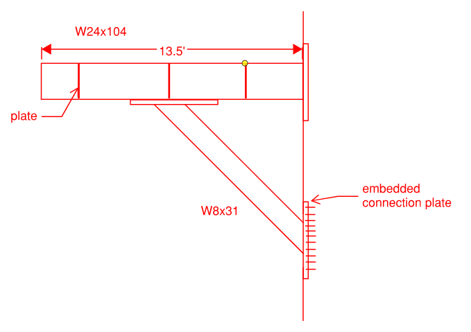
Capture_nywjx7.png

Thanks in advance!
 
Replies continue below

Recommended for you

If you think the bottom is fixed just use the approximate effective length factor for fixed - pin. I think most would just say pin-pin and be done with it.

This isn't really a 'frame' as far as the alignment charts are concerned, I wouldn't bother going down this route. Inspection of the equivalent effective length factor table by AISC should give a close enough approximation for this application.
 
I'd be going pin-pin. On a short item like that, what could you potentially save? Maybe 20 lbs in steel? Not worth the effort.
 
I am following the AASHTO LRFD Bridge Design Specs Section 6.9.4.2.1. I need the Kx and Ky values. What would be the appropriate values for this if i assumed a fixed-pin case.
 
ac0609 said:
I am following the AASHTO LRFD Bridge Design Specs Section 6.9.4.2.1. I need the Kx and Ky values.

Kx = 1.0; Ky = 1.0. Just as the other gentlemen said.

ac0609 said:
What would be the appropriate values for this if i assumed a fixed-pin case.

Theoretically 0.7 but most folks take this as 0.8 to acknowledge that nothing is ever perfectly fixed.
 
Since I am assuming a Fixed-pin condition then both Kx and Ky would be 0.8?
 
ac0609 said:
Since I am assuming a Fixed-pin condition then both Kx and Ky would be 0.8?

Yes, if you feel that same fixity is justified in both directions.
 

Im only asking because the lead engineer wants me to actually use the alignment charts and it just wasnt making sense since this is a diagonal beam.
 
Pesky lead engineers...

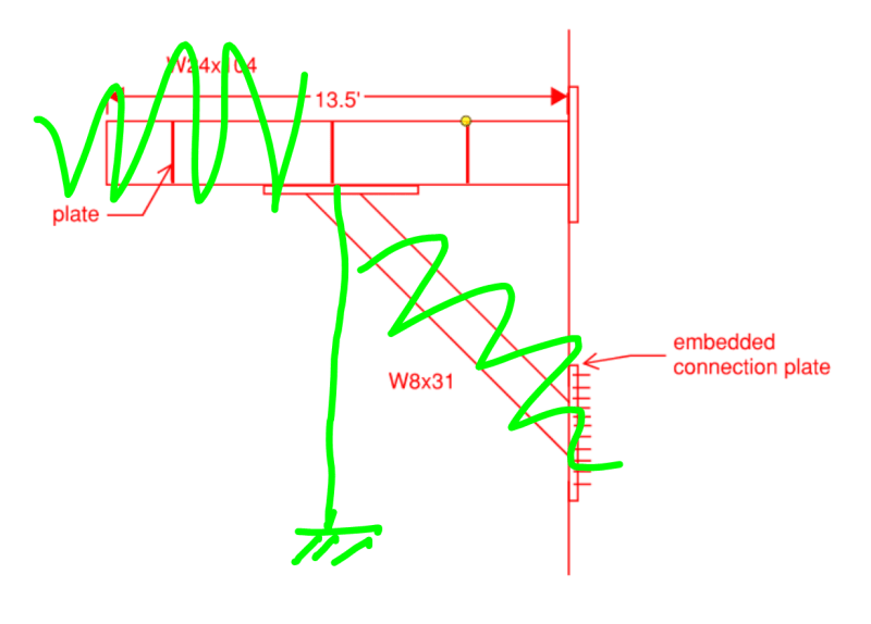
Fine, use the alignment charts. Other than practical design efficiency, I see no reason that you couldn't do it as I've shown it below. Maintain the length of the W8x31.

Capture_ippdsw.png
 
Just consider that for the alignment chart per @KootK's last sketch, the top of the kicker brace needs to be rigidly connected to the W24, their rotations must be compatible.
Also for your out of plane direction seems like you would be looking at a fixed pinned scenario, that is surely going to control if you have the W8 flanges on the top and bottom in your sketch.
 

Okay thanks a lot. Yeah the flanges are at the top and bottom.


How come you crossed out the section of the W24 to the left of the W8? Do i just take into account W24 section to the right?

 
ac0609 said:
Do i just take into account W24 section to the right?

Yup. I was just trying to simplify the problem as much as possible by eliminating extraneous things.
 
That side of the beam wont contribute to the rotational stiffness at the joint anyway (in absence of loading).
 

Thanks a lot. Lets see what I get
 

There is loading on top. I just didnt draw it in sorry. Theres a whole pedestrian path above it.
 
The loading won't affect what you do procedurally with respect to the effective lengths for buckling. What it will do is induce a moment at the top and bottom of your diagonal member such that the diagonal member will become a beam-column rather than a plain column.

Speaking theoretically rather than procedurally, the presence of loading will reduce the likelihood of buckling in whatever direction would increase the potential energy of the loads the most. It creates a preferred direction of buckling when all other things are equal.
 
Status
Not open for further replies.

Part and Inventory Search

Sponsor