Continue to Site

Eng-Tips is the largest engineering community on the Internet

Intelligent Work Forums for Engineering Professionals

  • Congratulations SDETERS on being selected by the Eng-Tips community for having the most helpful posts in the forums last week. Way to Go!

Effective Length of a Bottom Chord when a Mixture of Tension and Compression Present 1

Status
Not open for further replies.

ENGUCR

Structural
Sep 23, 2017
37
Hi,
I need a bit of advice on the selection of effective length for the compression capacity calculation of bottom chord of a truss(double inverted) when there is a mixture of tension and compression in this chord member. Please see the attached axial force diagram. What length should I use for this out of plane buckling? is it the entire length of chord member or the segment length of the compression part?
Tx in advance
 
 https://files.engineering.com/getfile.aspx?folder=d4007882-1808-4643-85d8-54e57271b1ef&file=Annotation_2021-01-06_181803.jpg
Replies continue below

Recommended for you

Kootk said:
Exactly. Some will not use appropriate member connections and will rely on floor diaphragms and other stuff inappropriately for stability. If you think that it is your, personal work that represents my concern here, then I'm afraid that you're not really picking up what I'm attempting to lay down.
No. I didn't interpret it that way. I just have a different perspective, though I can relate to your perspective.

Kootk said:
You've been here a while. Surely, you've noticed that there are plenty of engineers floating around that struggle mightily even with appropriate, linear elastic modeling, yet alone the fancy stuff?
Yes, incompetent engineers are a worry. Though it isn't clear to me that I the fancy stuff is more easy to get wrong than the traditional stuff. The pitfalls are different but not necessarily more challenging.

Kootk said:
Traditional methods like the effective length concept of course. It can, like anything, still be done badly but it is at the lower end of the complexity curve for sure. And, at the very least, it is a method that is universally undertaken with deliberation, if not skill.
Personally, I would struggle with a whole bunch of 'traditional stuff'. It just hasn't been the way I've learnt or practiced.

That said I was a poor student in my tertiary studies and I've had zero mentorship. I've just been careful to stay within my capabilities and certainly discussions like this help me to become a better engineer.
 
Agent666 said:
Never used DAM in anger though, but I can appreciate it lends itself to a certain type of problem.

Ha! I would have starred that were I one to give out stars for non-tech contributions.

Agent666 said:
Correct me if I'm wrong, but you still have to have a good feel of how it's going to fail/buckle to apply the notional loads in a manner that promotes the same (critical) buckling mode if you like.

You are not wrong in that the more exotic structures will require some skillful creativity in order for DAM to be applied. There are limits to how much you can dummy proof a complex thing. I was thinking more along the lines of structures like buildings where the lateral loads and stability demand are diaphragm dominated. There, it really is easy bake. I'll see if I can teach my new puppy to do it and report back.

Agent66 said:
The DA method makes perfect sense in terms of how intuitive it is supposed to be, effectively modelling the point of buckling and ensuring you have sufficient strength at that performance point.

I agree, although I feel that both moment magnification and bifurcation have things of value to add to the story. Moment magnification has the benefits that you mentioned but, in my opinion, doesn't drive home one very important point quite the way that bifurcation theory does: compression reduces apparent flexural stiffness and, when that apparent stiffness goes to zero, some really bad things can happen really fast. That's certainly implied in moment magnification but you have to look harder for it.

I've always found it interesting that concrete column design had the moment magnification thing sorted long before anyone was talking about DAM. My guess is that steel and concrete went in different directions with respect to column buckling because of concrete's inherently more non-linear, approximate nature.

human909 said:
Personally, I would struggle with a whole bunch of 'traditional stuff'.

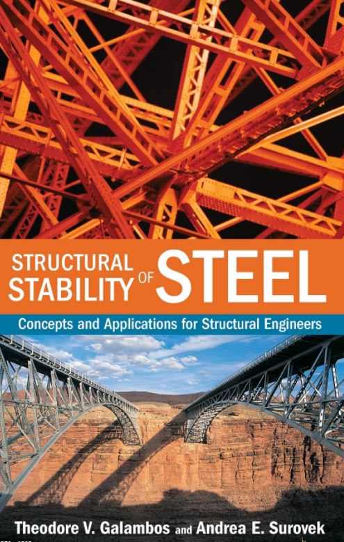
The best at anything are always autodidacts at heart. If you're ever curious about the traditional stuff, check out the book below by one of the godfathers of structural stability. It's short, concise, and the appendix includes a formal derivation of the K-factor alignment charts which is enlightening. One nice thing about a dead-ended technology is that, eventually, someone writes the definitive summary and then it just ends there. No need to worry about keeping up with future developments. As far as I'm concerned, this book is that for traditional, elastic frame stability.

C01_mvtirv.jpg
 
Agent666 said:
Never used DAM in anger though, but I can appreciate it lends itself to a certain type of problem.
The Australian steel code isn't too far removed from direct analysis, since the 1990 version. It requires second order analysis, notional loads, and uses K=1.0 in the combined actions check. The use of K>1.0 is applied to just the axial compression (assuming zero bending moment) as the AS procedure would overestimate capacity for small-moment members (at least according to Trahair). I presume that the reduced stiffness in DAM is the final piece of the puzzle that overcomes this, since DAM doesn't have the pure compression check.

If the NZ code is similar, it might be close to being a DAM nation.

KootK said:
compression reduces apparent flexural stiffness and, when that apparent stiffness goes to zero, some really bad things can happen really fast.
I'm one of the people who think the other way. To me, it was always increasing moment rather than reducing apparent stiffness, and buckling was the point where it became positive feedback. I struggled with the ideal Euler explanation because I always got hung up on the real world imperfections and "isn't it just failing in bending?" I feel bit vindicated by DAM.

MIStructE_IRE said:
i’d have stuck in a bottom chord brace and taken the effective length as 0.85 x unrestrained length.. Job done
I had the perspective that there was nothing to brace to. The last couple of times the elastic buckling analysis has been most useful to me were catwalk-type structures (pony truss) where a brace to the other truss would have been in the travel path.
 
Kootk said:
The best at anything are always autodidacts at heart. If you're ever curious about the traditional stuff, check out the book below by one of the godfathers of structural stability. It's short, concise, and the appendix includes a formal derivation of the K-factor alignment charts which is enlightening. One nice thing about a dead-ended technology is that, eventually, someone writes the definitive summary and then it just ends there. No need to worry about keeping up with future developments. As far as I'm concerned, this book is that for traditional, elastic frame stability.
Thanks. I've just had a good look online, that looks quite useful to have on my shelf.

Oh and I had to google 'autodidacts' to know what it meant. [bigsmile]

Kootk said:
I was thinking more along the lines of structures like buildings where the lateral loads and stability demand are diaphragm dominated.
Interesting... And maybe this is somewhat highlights our differing perspectives. I pretty much have never relied on diaphragm behaviour in my short career. Mostly industrial steel structures with plenty of penetrations. Sure in quite a few case I could probably get away with some, but you never know when additional penetrations are going to be added.

 
steveh49 said:
I'm one of the people who think the other way. To me, it was always increasing moment rather than reducing apparent stiffness, and buckling was the point where it became positive feedback.

Well, there's certainly nothing untrue or inaccurate about any of that. It just represents a particular, highly practical angle of attack. Even with ideal, Euler buckling, nothing happens until there's a perturbation of some sort. And that perturbation can be an applied moment just is it can be in imperfection etc.

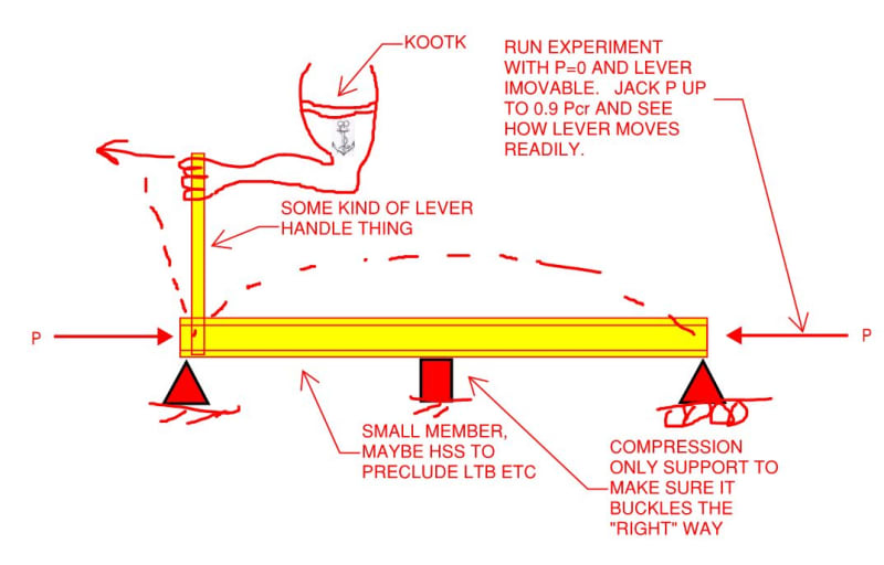
With regard to compression's impact on apparent flexural stiffness, I've always felt that the stability lab demonstration shown below would rock some worlds if it could be set up safely. Heck, if a few graduate students had to perish in the service of scientific discovery, so be it.

C01_x7p4qr.jpg
 
And yes, I suffered from childhood scoliosis of the forearm.
 
For those who have tuned out a little would you mind elaborating slightly on your comment. Thanks in advance.

KootK said:
I've always felt that the stability lab demonstration shown below would rock some worlds
 
Sure. I feel that this would be bloody astounding to feel, literally, in my own hands: the apparent, rotational stiffness of the beam changing with increasing axial load.

c02_pu5bh5.jpg
 
steveh49 said:
That might have made me think the other way.

Great, it's designed to fascinate and enlighten, not necessarily encourage any one perspective.
 
One 'tool' I've often used to demonstrate buckling is the inside of a standard BIC ballpoint pen. So I've now spent the last two minutes running your little experiment. The reduction in flexural stiffness is quite apparent both with an end moment and a centre point force.
[2thumbsup]
 
Does it work? I kind of live in perpetual terror that, push come to shove, it might not.
 
It works quite well. (The centre point force is not as obvious if you just use you fingers because of the low loads involed but then if you use the outside of the BIC pen as a lever arm it becomes quite apparent.)

Who needs these fancy apparatus when you have this on your desk. It works for the calculations and for the experimental apparatus! :-D
220px-03-BICcristal2008-03-26_v4ugav.jpg
 
Is it really the case that the flexural stiffness is reducing? I know it feels softer, but isn't that because Axial load P is already loading the beam in a way that will drive the beam into a buckled shape, meaning there's less work required when bending the lever?
 
Tomfh said:
I know it feels softer, but isn't that because Axial load P is already loading the beam in a way that will drive the beam into a buckled shape, meaning there's less work required when bending the lever?

Yup. That's the "apparent" in the apparent flexural stiffness that I keep mentioning diligently. E, I, & L obviously remain the same throughout the process. This is, however, precisely the effect that the geometric stiffness matrices are capturing.
 
Tomfh said:
I know it feels softer
Lol. I'm just now imagining Tomfh and half a dozen people reading this thread across the globe playing with a pen at their desk. [bigsmile]

KootK was diligent in his use of 'apparent' but it you readily be argued that the preface is unnecessary. Afterall the traditional definition of stiffness is k=F/Δ. (Though as structural engineers our typical response on what determines a beams stiffness may tend towards E/I/L and boundary conditions. Axial compression isn't a typical response.
 
Ok fair enough. I understand what you guys mean now by reduced stiffness, be it “apparant” or however we choose to characterise it.
 
Status
Not open for further replies.

Part and Inventory Search

Sponsor