Continue to Site

Eng-Tips is the largest engineering community on the Internet

Intelligent Work Forums for Engineering Professionals

  • Congratulations KootK on being selected by the Eng-Tips community for having the most helpful posts in the forums last week. Way to Go!

Effective length of column 4

Status
Not open for further replies.

civileng01

Structural
Jun 26, 2018
14
I am assuming the column is pinned at both ends and taking the column as a beam for approximate analysis. the length is 7m and I want to take the effective length (3.5m) to reduce buckling, do I use 3.5m length from the start of my calculation from finding reactions, sf, bm and so on.. or only use (3.5m) when finding buckling check?

in real life how is the length reduced to an effective length of 3.5m when it is actually built to 7m?
 
Replies continue below

Recommended for you

If the column is physically 7m, all of your reactions/shear diagrams/bending diagrams need to be based on a 7m length.

{The following assumes a traditional effective length method (e.g. K-L) analysis}
The effective buckling length of a column may be more or less than the physical length between braces, depending on the end support conditions. If pinned at both ends and with no braces between the ends, you must use 1.0 * the physical length. The only way to reduce the effective length is to provide a suitable brace between the two end points, or to provide fixity against rotation at one or both of the ends.

(Note, different boundary conditions may also affect the reactions/shear diagrams and bending diagrams mentioned earlier).

Additionally, other methods, like the AISC direct design method, are available to consider the effects of member unbraced lengths or second-order effects. These methods often can be used to obtain less conservative results when they apply.

----
The name is a long story -- just call me Lo.
 
Add horizontal connecting beam between columns and "X" brace at least at one bay. The effective length can be reduced around one axial (normally weak axial). The other direction you can design moment connection between beam/column, I am afraid it can not help too much.

—————————————————————
J&J Structural Consulting Inc.
Structural design, analysis, inspection, drawing review and stamping, and connection design
 
thanks for advice I have cone to deflection the only problem is the actual deflection exceeds the assumed deflection when using length=7000mm but when I reduced it to 3500mm the deflection check was ok. so is it okay to use 3500mm assuming effective length for deflection is that incorrect. if I change the steel section the new section will be so big for my structure. I have done the bending and shear resistance they are ok with when using 7m length.
 
no....the effective length does not equal the analysis length of the column. The effective length when adequate bracing has been designed and installed impacts the load carrying capacity of the column for failure modes such as buckling.

Your shears, moments, slopes, and deflections will all still be based on the full 7000 mm length of the column.

Alternatively if you place additional framing @ 3500 mm and that framing is capable of resisting the reactionary forces and has adequate stiffness you could then look at the column as a continuous beam-column with two spans of 3500 mm.

Open Source Structural Applications:
 
OP said:
in real life how is the length reduced to an effective length of 3.5m when it is actually built to 7m?

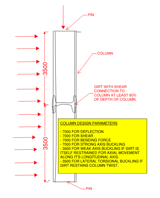
By pinning the column at mid height.

BA
 
if I pinned the column at mid height can I just analyse one part(3.5m) as simply supported? instead of analysing full 7m column, there will be a beam running the mid column and will add bracing. will that be ok? Or if i cantdo that will i have a 7m span with 3 reactions spaced at 3.5m?
 
@OP: based on what you've written here so far, I suspect that you have some serious and fundamental misunderstandings to sort out. I'd recommend stepping away from this thread and asking this question of an engineer who's face you can see. For what it's worth, I am one who makes this kind of recommendation very sparingly.
 
If the column is continuous with the midpoint pinned, any rotation at the pin will result in an equal and opposite moment above and below the pin and zero moments at both ends of the column. If the column is broken at the midpoint, i.e. completely hinged, one 3.5m section of column behaves as simply supported, and the bracing system provides any reactions required for equilibrium.

BA
 
"...taking the column as a beam for approximate analysis..."

Out of a large selection above, I find this comment most perplexing.
 
Always a fine line between being helpful and respecting the requirement to "not feed the animals". Please combine this with my original recommendation as the odds are excellent that I've missed something or assumed something incorrectly.

c001_rhhrbb.png
 
As per the drawing the column in one direction has alength 7 m and other direction 3.5 m by assuming it is pinned in bot end. If there is no beam in the middle it shall be 7 m in both direction. Considering if the mid beam is weak and can not prevent the lateral buckling so you must neglect it in your calculation.

 
Correct me guys if I am wrong but Effective Length does not play a part in the calculation of forces, the actual structural analysis (for loads) or any movement or distortion magnitudes. Effective length is only used when you have determined the forces in the member and are now doing your material check (steel, wood etc). Is the value of "K" actually in the stiffness matrix?
 
Ron247 said:
Correct me guys if I am wrong but Effective Length does not play a part in the calculation of forces, the actual structural analysis (for loads) or any movement or distortion magnitudes.

If the effective length of a column is reduced by pinning the midpoint, then under an arbitrary set of applied loads, the shear, moment, slope and deflection will all change.

BA
 
I know adding pin will will change the forces in the column, but the K-value used to calculate the "effective length" is not part of the stiffness matrix values is it? In other words, adding a lateral flange brace to reduce lateral buckling does not change forces, it changes allowables. The end conditions (pinned vs fixed) are already reflected in the degrees of freedom.

Maybe I am confused on what Civil is doing. Are they adding a support or a lateral brace? And I do not understand "taking the column as a beam". I am envisioning the situation being as depicted in KootK's drawing.
 
a note of caution...if you have bending in the column, ensure that you dont half the lateral torsional bucking lenght if the brace and connection cannot transmit the small moment at that connection. a simple shear connection as shown in kootk sketch may or may not be suitable for this purpose.
 
I think the OP has to come to our rescue and tell us more precisely what he is asking. It isn't clear to me.

BA
 
ron said:
In other words, adding a lateral flange brace to reduce lateral buckling does not change forces, it changes allowables. The end conditions (pinned vs fixed) are already reflected in the degrees of freedom.

Certainly, I agree with this as a general statement. And it's a very important point for OP to recognize if she doesn't already.
 
Status
Not open for further replies.

Part and Inventory Search

Sponsor