Continue to Site

Eng-Tips is the largest engineering community on the Internet

Intelligent Work Forums for Engineering Professionals

  • Congratulations KootK on being selected by the Eng-Tips community for having the most helpful posts in the forums last week. Way to Go!

Effective Length of Sway Uninhibited Multi-level Columns 3

Status
Not open for further replies.

Forgot2Yield

Industrial
Feb 10, 2022
65
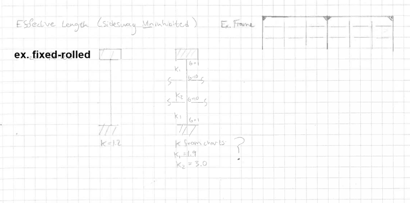
Hi, I've been trying to understand how one would go about assigning effective length factors to columns in sway frames when all the intermediate floor beams are pin connected to the column? Would it be like I have shown here?:

2024-05-23_14h33_38_jkj6wp.png


Would I split the column up into sections and use G=10 and G=1 for the joints or would I just ignore the intermediate members completely if they are all pinned and use the entire length of the column with K=1.2?
 
Replies continue below

Recommended for you

Of course, my example was simple and never occurs in practice as such. But it is not that rare in my experience to have a bracing system at the two extreme ends of a structure with middle frames relying on the outer braced ones for stability. It's similar to "column and a wall" in a sense that two stiff members (similar to a wall) are bracing multiple flexible ones (similar to a column).
If you ignore snap-through buckling and out of plane behaviour (also assume a rigid diaphragm), the two outer frames (with braces) have a sway type of deformation and the middle frames with no braces have a non-sway type, right?
 
I think the current treatment of that is there's a notional lateral load (from gravity load) that imitates the bracing forces that is added horizontally to the structure at the "leaning" columns, this then has to be resolved through the diaphragm into the lateral system, with the appropriate direct lateral forces (wind/seismic) added appropriately. The lateral system has either analytical requirements or a penalty to the stiffness (and maybe strength?) to account for it with reasonable accuracy.

A How-to Approach to Notional Loads, Ericksen, Modern Steel Construction, January 2011.

You might be able to track down more current articles from there, let us know if you find anything newer....
 
Braced frames don't have sway deflection. Lateral stability is provided by the braced bays through axial force in the brace and columns. It's not infinitely stiff so there is lateral movement but this isn't sway deflection. If you design by the effective length method you check each column for its own load with K<=1.0.

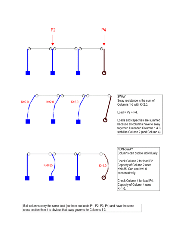
Now change the braced bays to moment frames. Lateral stability is provided by bending in the moment frames. This is sway deflection and the deflection is more than for the braced structure. The middle columns also have to sway because they follow wherever the moment frames go. For sway buckling, you use K>1.0 for the columns in the moment frames and you have to include the load on the middle columns in this check as well as the load on the frame columns. You don't need to check the middle columns for sway buckling because they aren't providing sway stability.

If the moment frames are good enough to prevent sway buckling then you have to check each column for non-sway buckling with K<=1.0 and each column's own load.

If you use notional loads and non-linear analysis then you don't have to use K>1.0 but check your code allows this. This is because the K>1.0 check accounted for the analysis giving bending moments that are too small because structure imperfections were ignored.
 
Smoulder said:
If the moment frames are good enough to prevent sway buckling then you have to check each column for non-sway buckling with K<=1.0 and each column's own load.

This is perhaps poorly worded in an attempt to be all-inclusive.

You would not normally check the gravity columns for K<1.0. You'd check them for K=1.0 (or the equivalent treatment in the current code). They are pinned-pinned. If they had a K less than one, they'd be moment connected top and/or bottom and would have a K>1 because they'd become part of the lateral system. K less than one is for fairly unusual situations involving braced elements that have unusual fixity at the top and/or bottom. Relatively few designs consider the base to be fixed, unless we are talking about cantilever columns, and cantilever columns are the lateral system at least partly if not totally (think most gas station canopies), and should not have a K=1. K should be greater than one due to the lack of bracing and the column is able to sway.

Smoulder said:
If you use notional loads and non-linear analysis then you don't have to use K>1.0 but check your code allows this. This is because the K>1.0 check accounted for the analysis giving bending moments that are too small because structure imperfections were ignored.

"structure imperfections" isn't really what's being dealt with here, or I feel compelled to quibble or be pedantic. This is perhaps arguably true, but it's a question of emphasis, as it's not a primary objective of the direct analysis. The P-small delta and the overall column compression tables account for residual stress and they account for some initial imperfections in the member. They probably account for some out of plumb, as well, due to erection tolerances. B[sub]1[/sub]/B[sub]2[/sub] was a way to create an approximate second order analysis from a first order analysis, including K factors (after the fact, as a "post-processing" mostly manual check of the member to confirm the design worked after the analysis), to account for structural movement (under load cases), that a first order analysis did not capture (as well as account for some effect of softening of the structure due to column plastification when under [primarily] high axial loads). Keep in mind a true B[sub]1[/sub]/B[sub]2[/sub] would include artificial restraints on the no-translation model (to get the M[sub]nt[/sub] (no translation) moments), and two separate analysis runs, that you then manually combine, with B[sub]1[/sub]/B[sub]2[/sub] to determine the column is acceptable. I don't think anybody ever coded this and I'm not aware of a software at the time that would do it, at least not automatically because you have to appropriately restrain the frame to prevent lateral translation.

The advanced analysis is intended to (speaking from recall) "eliminate" K factor consideration by implicitly accounting for destabilization of the column due to structural movement (i.e. second order analysis (Generally this implies multiple load steps, calculating deflections, and iterating "upward", including P-large delta, P-small delta (geometric stiffness), story drift, there's also provision for plastification in the analysis and the more sophisticated analysis engines should have a way to "step back" if a load step goes "too far" beyond the failure surface on a column so that the column stays "on" the failure surface, as of say 2000 this was a bit of a computational mess, if you ask me, I know I had a lot of trouble dealing with the failure surface coding) directly, so the K factor is still "there" so to speak, but it's not explicitly calculated, you can back calculate it if you are curious, as far as I know, if you have enough information from the software.

I had a class on advanced analysis ("direct analysis" in the current nomenclature) otherwise I wouldn't be wading into this discussion so pedantically. That class worked off the Ron Ziemian Ph.D. thesis "Advanced Methods of Inelastic Analysis in the Limit States Design of Steel Structures", (this is the current editor of the Stability Design Criteria for Metal Structures guide, I think). I still have that in the garage archive. The thesis, I mean.

Should anyone be interested the first 24 pages (no formulas) of the Dissertation is available through the link above.


 
@lexpatrie I agree, your definitions seem logical to me. Anything not part of the lateral system buckling length is equal to the vertical spacing of diaphragms. Anything that is part of a lateral system is subjected to sway (because nothing is holding it from deflecting).
 
The gravity columns should move laterally, but they would be braced by the diaphragm above and the effects of the sway are accounted for by penalizing the moment frame/braced frame/shear wall (via the notional loads and direct analysis) and the gravity columns are close enough with K=1 (or whatever the current code language is).
 
@hardbutmild: with respect to your wall and column example, I would put things this way:

1) Fundamentally, the lateral systems of all buildings are "sway". All lateral systems cantilever from the ground and are free at the top unless we're getting into exotic, dynamic stuff with mass tuned dampers etc.

2) Code classifications of [SWAY vs NON-SWAY] is simply about guiding designers as to whether or not the amount of sway and moment amplification expected warrant explicit consideration by designers with respect to global building stability.

3) Laterally flexible vertical framing elements, like the column in your example, will tend to be "shielded", to some degree, from participating in resisting lateral loads by the inclusion of much stiffer lateral elements in the same load path (the wall in your example). Some codes provide guidance with respect to what level of differential element stiffness (wall vs column) is required for the column's, non-zero participation to be deemed small enough to ignore. More often, this simply requires designer judgment.

4) Unless gravity columns are truly pin-pin, which they almost never are, then the drift at the diaphragm levels will induce moments in the columns and force them, to some degree, to participate in resisting global building lateral loads. This is one of several good reasons to limit the drift of the designated lateral load system. It is the drift control provided by the designated lateral system that justifies the treatment of the gravity only systems as laterally supported at the top(s) rather than cantilevering.

5) Even a truly pin-pin column will be affected by the drift of the diaphragms that support it laterally. This is because the angular, rigid body tilt of the columns will slightly increase the axial load in the columns. That said, if you've got enough drift for this to add up to anything, then you've got bigger problems to worry about.

6) Yeah, keeping in mind all of the nuances listed above, practical situations usually result in:

a) Laterally stiff vertical elements such as walls are generally used as the designated lateral system with K >= 2.0 as befits a cantilever.

b) Laterally flexible vertical elements such as posts used in conjunction with stiff walls are generally designated as "gravity only" with K <= 1.0 as befits a member with lateral restraint at both the top and bottom.
 
Why do you guys keep saying K<= 1.0???? This less than is killing me.
 
lexpatrie said:
Why do you guys keep saying K<= 1.0???? This less than is killing me.

Please elaborate. If it's more efficient, just point me to the particular section where you've explained your position above, if you have, and I'll review it with care.

Using the effective length method for a member without relative, end to end translation (gravity post) results in [0.5 <= K <= 1.0] by definition. 1.00 represents perfect pin-ended-ness. 0.50 represents perfect rotational fixity. Everything else -- the real world that is -- falls between those extremes.
 
Great post KootK, you explained it in a simple way and it makes perfect sense. I thought I was going crazy when looking at codes and books on that topic.

@lexpatrie Why not <1? Imagine a frame with huge beams and very small columns (frame is of course braced by another stiff member).
 
These (gravity columns) are typically designed as pin-pin, so K=1, hence my continued complaint about folks saying K<=1.0. It's not meaningfully less than 1.0. You aren't going to have G[sub]B[/sub] = 0 (infinitely fixed base) on anything, a pinned base is G[sub]B[/sub] = 10 in a practical sense, and when the column isn't designed to have any restraint (simple beam connection) there's G[sub]T[/sub] = infinity (in theory) and perhaps 10 in "hypothetical practice", but outside academia a gravity column is K=1.0. You wouldn't normally even "do" a K factor on the gravity columns, you'd use 1.0. Unless there's something really odd going on in typical practice and nobody told me. You won't get much out of K=0.99 versus 1.0.
 
Ok, fine, let me go get my nomograph from the garage.

1st ed LRFD, "If the column end is rigidly attached to a properly designed footing, G may be taken as 1.0. Smaller values may be used if justified by analysis."

Yeah, 0.85 isn't too far off, with G[sub]B[/sub] = 1.0, G[sub]A[/sub] = infinity. That's an unrealistic design scenario, however, fixed bases at random columns in a building that aren't part of the lateral system are (highly) unconventional. I maintain my point. The infinity at the top is rather dominant and pushes the K factor to the closer side of 1.0, even with a pinned base, G[sub]B[/sub] = 10, the K factor doesn't move that much off from the top end of the scale. Hence, most engineers won't bother/don't bother.

Turns out that subscript is a capitol letter, too. Nuts. Revising...

For that second figure, the sway figure, recommended K is 2.1, not 2.0 See Table C-C2.1, 1st ed LRFD (case (e)).
 
I am surprised this topic has generated so much debate and discussion. Then again, I was one of the causes the longevity of this thread...

lexpatrie said:
These (gravity columns) are typically designed as pin-pin, so K=1,
Which is conservative and doing so is your prerogative. However as has been well argued by kootk:
[0.5 <= K <= 1.0] by definition. 1.00 represents perfect pin-ended-ness. 0.50 represents perfect rotational fixity. Everything else -- the real world that is -- falls between those extremes.

We live in the real world and effective lengths less than 1.0 are common in a system largely without sway.

lexpatrie said:
fixed bases at random columns in a building that aren't part of the lateral system are (highly) unconventional.
For the purposes of determining an effective length of a gravity column most bases are effectively 'FIXED' and do not behave in a pinned fashion under pure gravitational loads. Also if you are dealing with floor of different heights then the effective length is k<1 for a taller floor which has smaller floors above and below it.

Again how conservative you want to be is your choice. But if you always choose k=1.0 then you are quite likely not designing things as economically as they can be.

All that said I largely design my steel with effectively lengths software calculated. It is not worth my time to manually input effective lengths and it is also potentially unconservative in some cases. The approach used by the software to calculate effectively lengths is on the conservative side so I usually end up with k=>1 for most members. But the software will tend towards k=.7 or k=.85 for critically loaded members that are suitably restrained.
 
@Lexpatrie I used cantilevers because they're simple. No frame action and don't need the graph for K. OK America uses 2.1. I thought 2.0 off top of head. That was Britain. Australia is 2.2. Doesn't really matter to the principle. You wanted to know when K<1. When effective length is used for sway design (K>1) and you check total vertical load against sum of column capacities AND some columns are heavily loaded and some are lightly loaded then you should also check nonsway for individual columns with heavy loads using K<=1. Sway still often governs.

Cantilever columns do exist like timber pole houses and bridges. Poles/piles are driven into ground and carried up to structure level. I've seen heavy loads on some but not all columns due to spa bath and overweight vehicle on wide bridge.

Same principle for moment frames except the rigid connection is at the top instead of foundation. Had one where equipment was moved. Some columns loaded more than original design and some less. Loaded some more than capacity with K=1.5 by using unloaded column spare sway capacity. Then checked the loaded columns with K=0.9 for nonsway.
 
@Human909 I think your method means all columns are equally utilised in compression member capacity. That right?
 
Smoulder said:
@Human909 I think your method means all columns are equally utilised in compression member capacity. That right?
By my method I presume you are referring to the software method I use. I use SpaceGass for steel structures, this their summary for how effective lengths are calculated.

To elaborate if that link isn't clear, it calculates effective length base of ALL members off the load in the first instance of Euler buckling of the frame. This approach does not rely on all columns being equally utilised, it calculates ALL effective lengths off the most utilised column (compression member). So it is a shorthand approach, but is conservative without being overly so. Occasionally, I get an output of minor compression member with inappropriately high effective length (an associated errors) but it isn't common and is easy to correct.

I have used few other software packages for frame analysis so I can't comment on how it performs relative to others. But I find it reliable and has been the leading software for AS code for decades.
 
OH anyway. Can we at least get all five dentists to agree that K=0.5 is generally not achieved?

This "pinned foundation is unrealistic" shows up almost as a meme on this forum. That it's unrealistic to treat it as pinned is fine, because doing so is conservative. That's fine, I guess. As far as the "treat it as fixed, always", I'm far less sold on. Like I said above, the K factor does not move all that much toward 0.5 based on the restraints, generally you are reasonably close to K=1.

The technical background on the subject that I'm aware of doesn't go much beyond "use G=10" versus G=infinity for a pinned base. You could hypothetically squeak out a little more capacity, but ...

Human909 said:
Again how conservative you want to be is your choice. But if you always choose k=1.0 then you are quite likely not designing things as economically as they can be.

I think you're overselling that. I don't design gigantic warehouses, a wall thickness or two, and the "spacing" between your various column designs (W14x22,W14x30, say), I'm not convinced is going to drastically affect a design, or even affect a design. You could probably contrive an example where it's an 8 plf difference between the two approaches, but I'd expect there's another example where it doesn't change the column size. I'm not adding a hypothetical 400 tons of steel and even so, we aren't talking about "my" design, I mean most engineers won't bother with trying to justify a K=0.86 versus a 1.0 in most designs, you guys want to shave the sides off it, go ahead.

At least you aren't designing the ballasted roof for 15 psf (yes, there's a firm that's doing that).

As a step back, "designing things as economically as they can be" isn't equal to least weight. It's also not a duty I am legally obligated to provide. I' not negligent when I design a pin-pin gravity column for K=1,0. Health, Life-safety, and Welfare. Squeezing four pounds (or a thousand) out of a 10,000 ft[sup]2[/sup] structure and then adding forty thousand dollars of web reinforcement, doublers, stiffeners, half the beams into the weak axis have to be double coped top and bottom to fit into the weak axis, and they have to knife them in from above, I mean, you do you. If this were such a miraculously clever approach to saving significant quantities of steel, how isn't there an AISC seminar on the subject? Why isn't it all over Modern Steel Construction and your various steel design guides?

I find it bizarre that half the discussions here I'm the "you need to be more literal" guy, and the other half the time I'm the "that's not going to get you much for the computational effort" guy. I guess that's okay. Maybe I should be reassured that I'm sometimes on the opposite side of a discussion.


lexpatrie said:
I think you're overselling that.
I wasn't trying to sell that. In fact if you read the full length of my post I rarely used effective length factor of less than k=1.

lexpatrie said:
As a step back, "designing things as economically as they can be" isn't equal to least weight.
I don't think anybody was arguing that is so.

lexpatrie said:
Why do you guys keep saying K<= 1.0???? This less than is killing me.
...
These (gravity columns) are typically designed as pin-pin, so K=1, hence my continued complaint about folks saying K<=1.0. It's not meaningfully less than 1.0.
The whole reason why this is being discussed is because you seem to not acknowledge that k<1 is a realistic possibility and that using k<1 can significantly increase your calculated capacity.

lexpatrie said:
OH anyway. Can we at least get all five dentists to agree that K=0.5 is generally not achieved?
Given that is the lower theoretical bound, yes. But again nobody was arguing to used k=0.5
 
Status
Not open for further replies.

Part and Inventory Search

Sponsor