Continue to Site

Eng-Tips is the largest engineering community on the Internet

Intelligent Work Forums for Engineering Professionals

  • Congratulations KootK on being selected by the Eng-Tips community for having the most helpful posts in the forums last week. Way to Go!

Effective lengths of a single angle x-brace

Status
Not open for further replies.

BendingMoment123

Structural
Apr 1, 2020
25
Hi all

In case 1, both members are in compression. In case 2, both members are in tension.
What would the effective lengths in respect of the angle's principal axes be (Lz = minor axis and Lv = major axis) for the following single angle x-brace connection?:
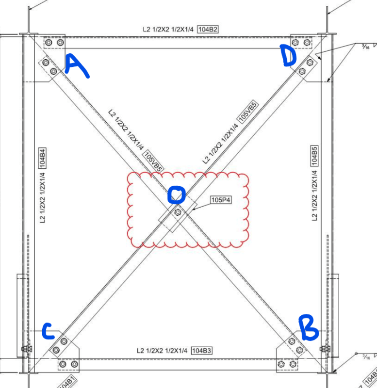
Screenshot_2021-12-07_144023_iqwn5c.png


Thank you
 
Replies continue below

Recommended for you

I have trouble visualising when both members can be in tension or compression at the same time.

Rather than think climate change and the corona virus as science, think of it as the wrath of God. Feel any better?

-Dik
 
Right there with you, dik. Sounds like there's either something really strange about that structure, or there's a boundary condition error in a model somewhere.
 
That diagram is not the structure I am dealing with (I just put it in to show the type of connection at the intersection). The x-bracing configuration in my structure is in the horizontal plane.
 
Doesn't change the fact that it would be strange to have both in tension at the same time. I'd be interested to see the actual configuration and a quick analysis by hand showing both diagonals in tension.
 
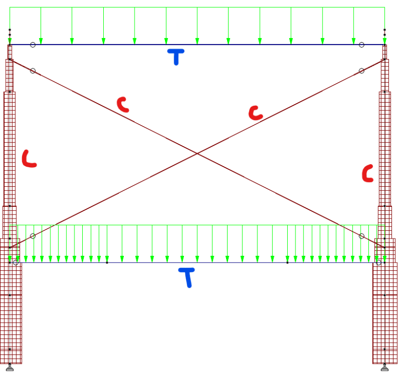
There is no lateral force acting on the structure, besides the notional load, to cause the member in the x-brace to be in tension and the other in compression. The brace is there to provide overall stability to the structure in the out of plane direction (but in the pic below, as I changed the view, the brace will provide stability in the in-plane direction). Here is a portion of the structure with the axial force diagram from STAAD with the only loads being a UDL in this case.
Screenshot_2021-12-08_153052_zpd6ik.png
 
That compression load is extremely incidental in a situation like that. The bracing is essentially there for stability only. The bulk, i.e. all, of the vertical load goes into the columns.
 
If both diagonals are in compression, you would neglect the point "O" bracing since both diagonals can buckle between the bolted ends at A, B, C, D and the unbraced for the Lz is the entire length. If both diagonals are in tension, there is no compression and UBL does not matter. In the case where one diagonal is tension and one compression, you can count on a weak axis out of plane brace at point "O" if the tension diagonal has more than 20% of the load of the compression diagonal. ASCE 10 has some examples for T-Line towers and how to compute compression capacity in the diagonals. We have very high lateral loads from the wind and wire tension and low vertical loads compared to a building. We use lots of single angle diagonals as well as corner leg angles, so we wrote our own book in ASCE 10.

_____________________________________
I have been called "A storehouse of worthless information" many times.
 
Bump up notional loads until one diagonal is in tension, and neglect the contribution of the other diagonal. What you are proposing should be resisted by tension only bracing.
 
Status
Not open for further replies.

Part and Inventory Search

Sponsor