Continue to Site

Eng-Tips is the largest engineering community on the Internet

Intelligent Work Forums for Engineering Professionals

  • Congratulations KootK on being selected by the Eng-Tips community for having the most helpful posts in the forums last week. Way to Go!

Effective Net Area - Shear Lag - CSA S16 interpretation

skeletron

Structural
Jan 30, 2019
857
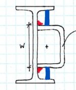
What is the interpretation of net section area for shear lag when there is an HSS (cut in half) or a channel section welded as per below?
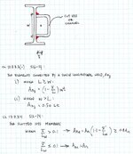
  • CL 12.3.3.3(b) is for "elements connected by longitudinal welds along two parallel edges". But, are the toes of the channel or top/bot of a cut HSS considered two parallel edges?
  • CL 12.3.3.3(c) is for "elements connected by a single longitudinal weld". In this case the efficiency factor is dependent on w (depth of HSS or depth of the channel).
  • CL 12.3.3.4 is for "...rectangular HSS members [slotted] and welded to a plate". In this case the efficiency factor is dependent on x_bar only.
In addition, when taking "L" or "Lw" in the above efficiency factors, how is this interpreted with a stitch weld?
  • Total weld length (e.g. # of stitchs x stitch length) or the required length for an equivalent stitch weld?
  • Total connection length (e.g. total length from first stitch to last stitch)?
  • Length of 1 stitch? If so, I would imagine the net section would need to be multiplied by the number of stitches...so possibly getting a big reduction factor that comes out in the wash once you consider the total stitches

Screenshot 2024-12-10 084359.jpg
 
Replies continue below

Recommended for you

I would lean to b. Certainly don't agree with 3.4 as there is a huge eccentricity in your connection not present in a knife plate connection. Stitch welds are highly unusual for tension members, why would you not put all the weld in one place?
 
CL 12.3.3.4 is for "...rectangular HSS members [slotted] and welded to a plate". In this case the efficiency factor is dependent on x_bar only.

That one under the presumption that it's about the eccentricity between the center of action of the axial force in the connected part combined thing.

Total weld length (e.g. # of stitchs x stitch length) or the required length for an equivalent stitch weld?

That one. We generally treat reasonably proportioned stitch welds as, effectively, linear things. Based on your recent questions, you've been thinking fairly deeply about the implications of stitch welding relative to continuous welding. And there is some nuance there. Just not nuance that we worry about in typical applications.
 
Drag strut connection in tension.
Existing W410 beams are spliced with a simple 3-bolt web plate. EOR wants to "bridge the gap" between existing beams with a drag strut for the new, upgrade forces.

You're right. I am beginning to see the light in stitches. Just needed to go through the rabbit hole before getting my gut feel in tune.
 

Attachments

  • Screenshot 2024-12-10 090832.jpg
    Screenshot 2024-12-10 090832.jpg
    32.8 KB · Views: 8
Gotcha. The setup looks to induce some weak axis moment in the beam as a result of the connection eccentricity. I imagine that's for the EOR to deal with.

What is it that you're bridging around with the channel? HSS column? I'm just curious at this point.
 
..Stitch welds are highly unusual for tension members, why would you not put all the weld in one place?

Mainly because these are field welds and the EOR is specifying anywhere from 600kN to 1850kN in axial load.
 
Gotcha. The setup looks to induce some weak axis moment in the beam as a result of the connection eccentricity. I imagine that's for the EOR to deal with.

What is it that you're bridging around with the channel? HSS column? I'm just curious at this point.

Existing beam-to-beam splices in most cases.
Yes, I certainly believe that the EOR should be considering the weak-axis moment in the beam as they are providing the general detail and they are providing the connection design force. I am screaming into the wind that they can't expect to drag the whole tension capacity of the beam just through a web connection...so I've made some modifications to give the axial load in the beam an "exit route" through the top and bottom flanges, where I believe that the axial load will be delivered to the member.
 

Attachments

  • Screenshot 2024-12-10 092339.jpg
    Screenshot 2024-12-10 092339.jpg
    40.8 KB · Views: 5
Mainly because these are field welds and the EOR is specifying anywhere from 600kN to 1850kN in axial load.
I think the welder will do it in stitches to limit heat but you end up with a continuous weld in the end, if you call out a continuous weld. You would also only have to set up to weld in one location
 
I am screaming into the wind that they can't expect to drag the whole tension capacity of the beam just through a web connection...
I don't agree with that at first blush. Yeah, connecting the entire cross section will be more efficient. But I'm sure there are spatial constraints making that difficult at the top flange. Doing the channel thing at least creates concentricity of deliver about one axis.

The other thing that jumps out at one here is that the channels will mess with the rotational ductility of the splice connection. I'll not fault the EOR on that though. These situations tend to have no perfect solution. As such, one kind of just does the best that they can.
 
I guess my opinion is based on the axial force originating from the floor diaphragm connection to the top flange. Up to a certain threshold, I'm okay with assuming there is decent distribution of the force to flow from the top flange into the web and then transfer through the welds to the channel/cut-HSS reinforcement. Once the design force starts exceeding the gross yield capacity of the web, I do start to look at it a bit more.

In this case, one of the splices needs to be designed for the full section capacity(**). I believe that giving a direct connection from the flange to the reinforcement does provide a redundant loadpath to the reinforcement that avoids dumping excess loading through the web. Not continuous plates (...that's a sequencing nightmare) but enough plate material and weld to justify that the flange capacity can be transferred to the reinforcement. I guess you could also do his discretely, with angles or smaller tubes or drag rods, but the access into that little pocket is tricky. The plate can at least be bevelled to allow for a weld from one-side.

Agree. These kind of connections feel like the EOR just wants "something" to get their primary force from point A to point B. It does seem like they are willing to get hand-wavey about certain details in the actual member design.

Screenshot 2024-12-10 131250.jpg

(**) EDIT: I should at least clarify that the one-sided reinforcement general detail does not work in this case and that there is actually access to the other side of the building. But my reasoning still stands for establishing a threshold before considering whether you need to bail out the web.
 
Once the design force starts exceeding the gross yield capacity of the web, I do start to look at it a bit more.
Sure, that make sense. I would think that it would largely be self-satisfying by the connection design however. Considerations like shear lag and section rupture should encourage enough connection length to make a plausible go of things.

I believe that giving a direct connection from the flange to the reinforcement
How long will those plates be? They would be quite long before I would feel good about the in-plane moment on them and the transverse bending that would imply in the beam flange and HSS wall.
It does seem like they are willing to get hand-wavey about certain details in the actual member design.
As a fellow who's done a lot of delegated design in recent years, I'm a firmly of the opinion that you mostly need to go limp and just help the EOR tell their story, as they see it. That, even if the story is not great. All other roads lead to mental health disorders.
 
Would something like this be very difficult to do from a fit-up perspective? The less axial eccentricity, the better IMO.

c01.JPG
 
Based on what I've seen of the exposed framing, your contraption could work but would certainly require the ironworker to cuss a bit here and there and/or bust out the torch. They're fine with the channel or cut-HSS because it's kind of goof-proof...EOR also sees it as representing their original intention, so I deal with less questions.

My flange plate design is actually short 3-1/2" deep plates (fit tight to u/s of flange) and 8" long. Placed at third-points or thereabouts on the reinforcing.
 

Part and Inventory Search

Sponsor