Continue to Site

Eng-Tips is the largest engineering community on the Internet

Intelligent Work Forums for Engineering Professionals

  • Congratulations GregLocock on being selected by the Eng-Tips community for having the most helpful posts in the forums last week. Way to Go!

Effective shear width for concentrated load near simple support

Status
Not open for further replies.

bugbus

Structural
Aug 14, 2018
506
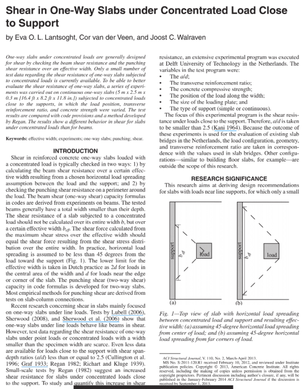
There's a number of research papers on this topic, many of them from the same Dutch authors Lantsoght, van der Veen, de Boer and Walraven.

The Australian codes are relatively silent on it, and I don't know what the standard approach is in the US or the UK.
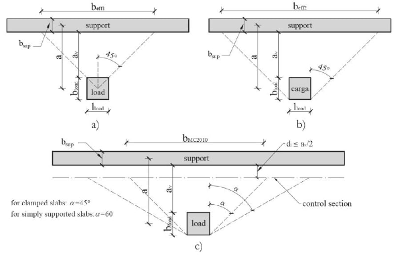
8c216950846bced92ff1c7ad57c5df2a03a0ed5b_znp8ai.jpg


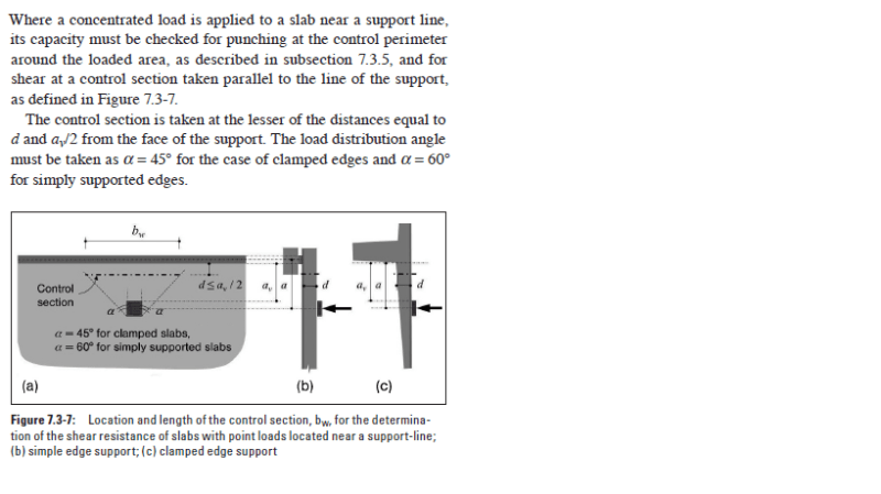
In the above, (a) is the 'Dutch' method; (b) is the 'French' method; and (c) is the Model Code 2010 method.

From my reading, the various Dutch authors seem to recommend (c) with a 45 degree spread as being the most accurate.

Does anyone have experience in this situation?
 
Replies continue below

Recommended for you


I would go with punching check.. As far as i know, EC-2 and ACI-318 are silent for this case. The following excerpt is from FIB MODEL CODE 2010 if you feel more detailed check is necessary..

Effective_slab_width_kzzico.png
 
I've been using the Dutch method under the impression that is still the state of the art.

In practice, most slabs wind up being clamped to some degree so the methods converge in that sense.

C01_kxuljt.png
 
OP said:
The Australian codes are relatively silent on it

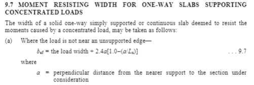
AS3600 Clause 9.7 has the formula for load resisting width for concentrated loads, which results in a value similar to 45 degrees.
 
Tomfh, that clause relates to a 'moment resisting' width specifically.

2_qibkvj.png


Maybe it makes sense to apply it to shear strength also.

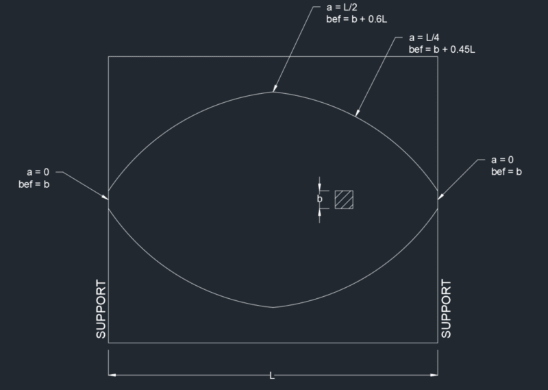
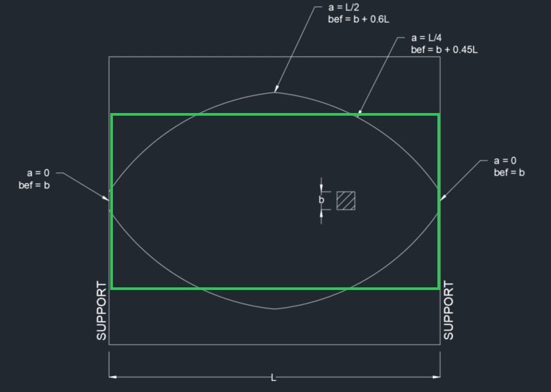
However, when I take that clause at face value, I interpret it to give the following effective width, which has a parabolic shape, not linear. And the effective width at the support (where a = 0) is equal to the width of the load patch:

1_cttltr.png


What I, and I assume many others, have in mind is a constant-width strip, with the width determined using 'a' at the position of the load patch. Possibly this is what the clause intends to do, but it is not worded that way. If this is the case, it should define 'a' as: perpendicular distance from the nearer support to the concentrated load.
 
The intention of AS3600 is a fixed width strip (beff) defined by the distance between the load and the support. The further your load is from the support, the wider the effective strip. Your plot is not a plot of the effective strip width at different positions along the slab, but instead shows how effective width changes as the load position changes.

826C0949-77FB-4C26-8DBA-91FB6E294888_mxhmqe.jpg


The commentary says to design for shear over this effective strip width too, which gives values close to 45 degrees as you move towards the supports.
 
Thanks for clarifying, I suspected that was the case

It seems that the AS 3600 approach is a bit more conservative than the MC 2010 approach then
 
Status
Not open for further replies.

Part and Inventory Search

Sponsor