Continue to Site

Eng-Tips is the largest engineering community on the Internet

Intelligent Work Forums for Engineering Professionals

  • Congratulations LittleInch on being selected by the Eng-Tips community for having the most helpful posts in the forums last week. Way to Go!

Effective Wind Area - Stud Wall with Parapet

Boiler106

Structural
May 9, 2014
207
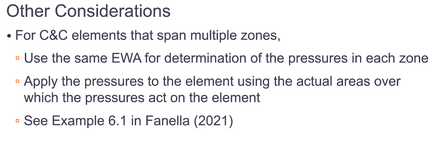
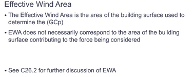
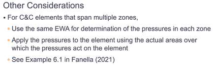
I have a stud wall that bypasses the roof line to form a parapet. Ive been using an effective wind area for the wall based on the overall length 21.1' to get 21.1'2/3 and use this value to get both my wind loads for the wall portion and the parapet portion.

Im second guessing myself and wondering if i need to use the parapet height 7'2/3 to get an effective wind area and a wall height, 14.1'2/3 which will yield a much bigger result. Thoughts?
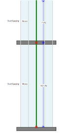

Screenshot 2025-03-13 133343.png
 
Replies continue below

Recommended for you

Normally I would say that the element is the entire stud and its effective area is calculated based on its actual length & span/trib but the parapet presents a different scenario.
How about ASCE 7-22 Section 30.6? And Figure 30.6-1.
The parapet wind pressure is much greater than the wall surface below the roof I think your design should account for that.
 
ASCE clearly defines the "span" from support to support. For further reading consult Guide to the Wind Load Provisions of ASCE 7-10 by Kishor C. Mehta, Ph.D., P.E. and William L. Coulbourne, P.E.. See Answer to frequently asked questions number 18 (quoted below):

"18. Metal decking consisting of panels 20 ft long and 2 ft wide is supported on purlins spaced 5 ft apart. Will the effective wind area be 40 ft2 for the determination of pressure coefficients?

No; although the length of a decking panel is 20 ft, the basic span is 5 ft. According to the definition of effective wind area, this area is the span length multiplied by an effective width that need not be less than one-third the span length. This gives a minimum effective wind area of (5)(5/3) = 8.3 ft2. However, the actual width of a panel is 2 ft, making the effective wind area equal to the tributary area of a single panel, or (5)(2) = 10 ft2. Therefore, GCp would be determined on the basis of 10 ft2 of effective wind area, and the corresponding wind load would be applied to a tributary area of 10 ft2. Note that GCp is constant for effective wind areas less than 10 ft2."

Good Luck
Interesting information, I'll need to read into it. It has been my experience that since it's a multispan situation you can use the full length for the C&C wind as I have seen commonly done by pretty much everyone I know. If what you state is true, then EVERY PEMB ever built is inadequate and improperly designed as they take full length of purlins and deck for C&C wind loading considering the purlin splices and deck splices as making them continuous spans.

In regards to decking spanning 5' between purlins, I would consider the C&C wind for connections to be 10 sq-ft, but not the deck typically.
 
Just FYI, PEMB manufacturers, or at least the major manufacturer I worked at, would not use the full length of the purlin to determine trib area. They would use the frame spacing x purlin spacing to determine tributary area on purlins. Wall panel pressure is girt span*panel width.

i.e. 100 ft long building with frames at 25' o.c. and purlins at 5' o.c., the PEMB engineers would use 125 ft2 for the trib area on the purlin, not 500 ft2. (They might use the L2/3, but wouldn't go larger than that.)
 
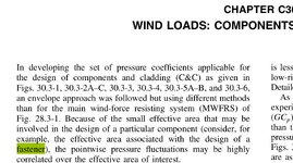
When it comes to connections, I do not follow ASCE 7 literally. If you do, you need to calcuate the effective area to an individual fastener which makes the wind load unreasonably high.
 
And to answer your original question, I have always used the entire height of the stud, including the parapet, to determine the C&C wind load.
 
Way too big. Should be area tributary to each fastener.
The reason I use 10 sq-ft is because that is the lower bound for the factors, not because the trib area is actually 10 sq-ft.
Just FYI, PEMB manufacturers, or at least the major manufacturer I worked at, would not use the full length of the purlin to determine trib area. They would use the frame spacing x purlin spacing to determine tributary area on purlins. Wall panel pressure is girt span*panel width.

i.e. 100 ft long building with frames at 25' o.c. and purlins at 5' o.c., the PEMB engineers would use 125 ft2 for the trib area on the purlin, not 500 ft2. (They might use the L2/3, but wouldn't go larger than that.)
Good info and good to know some of the players do it better. I don't recall who was the manufacturer on the ones I have seen recently using full length including splices.
 

Part and Inventory Search

Sponsor