Eng-Tips is the largest engineering community on the Internet

Intelligent Work Forums for Engineering Professionals

Effects on momentum on bearing rail in motion 1

Status
Not open for further replies.

ESTinker

Mechanical
Aug 24, 2017
39
0
0
US
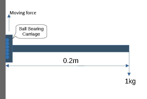
I got question on what is happening to the moment and forces on a ball bearing carriage with a lever arm. Basically the carriage is at rest and is moving/accelerating up and there's a load of 1kg at the end of the lever 0.2m from the carriage.

If it was not moving, the moment about the carriage is 1kg*0.2m=0.2kg*m (static problem), but once the carriage accelerates let's say 2G (gravitation force). I assume moment about the carriage will increase. So can someone explain what is happening once it starts moving and can the moment still be solved if we know the force used to move the carriage, in this case 2G?

Moment_Problem_vkr6ra.jpg
 
Replies continue below

Recommended for you

A kg*m is not a moment. Well, maybe a mass moment, but that's not a useful unit. Multiply by gravity, 1 g, or 9.8 m/s^2 to get about 2 N-m of moment. If the platform accelerates upwards at 2g's, then add that moment to the 1g from gravity to get 3g's or roughly 30 m/s^2, and the moment is around 6 N-m. How quickly the force is applied will affect how much the lever arm oscillates/vibrates, which it looks like it will, and that oscillation will depend strongly on the stiffness of the bearings.
 
does the blue (horizontal) wrap around the grey (vertical) ? if not, how does the ball bearing resist moment ?

"kg" (or "kgf") is an accepted unit of force ... how much do you weigh ? 100kg (or do you cross out "weigh" and put in "mass", or 1000N ?)
but yes, it is "sloppy" for engineers.

another day in paradise, or is paradise one day closer ?
 
rb1957,

I weigh 210lb and I have a mass of 95kg. I claim that these are two separate qualities that affect where you place g in equations, and furthermore, I claim that the OP's problem is a good example of this.

Weight W = mg.​

When it is not moving, the OP's lever arm supports a weight of W = 1kg[×]9.81m/s[sup]2[/sup] = 9.81N.

When it accelerates upwards at 2g, we need to add in the resulting force.

F = W + ma = 9.81N + 1kg[×]2[×]9.81m/s[sup]2[/sup] = 29.4N.​

While moving, your bending moment is

M = LF = 0.2m [×] 29.4N = 5.89N.m.​

Note how my unit balance would have revealed all sorts of confusion if I had not used the correct units.

--
JHG
 
1) of course mass and weight are different quantities. But in the general population, "kg" is frequently used for "kg_force, or kgf" as in a bag of sugar or your weight. Sure you could say "I buy 1kg mass of sugar" but few would understand your point. when someone asks your weight do you say "I have a mass of 100kg" ? Yes, I agree it is sloppy for engineers to use kg as force (and OP has explained it was done quickly, translating from lbf).

2) yes, I understand how to calculate a moment. My question was "how do the ball bearings apply this moment to the surface (if the carrier is not clamped to the vertical) ?" I'll get ahead of the argumentdiscussion ... yes, by a couple of distributed force. ok, the ball bearings can push against the vertical, but where's the other 1/2 of the couple ?

another day in paradise, or is paradise one day closer ?
 
ok, so there are two races supporting a load to the right (in the pic) ? Then (of course) each race reacts one of the couple forces (compressing against the track).

another day in paradise, or is paradise one day closer ?
 
Yes, the picture is of the bearing rail.

On a similar situation if I add a second carriage and lock them in a bracket as a static problem what is happening to the forces and moment at the top carriage?

At first I thought the moment would be just the same (-10N*.2m)=-2N.m but it doesn't seem right to me, as there's is a force pushing against the lower carriage so there is an moment there also right? Otherwise, the moment about the top carriage would be the same with or without the addition of the lower carriage and addition bracket support.

Moment_Problem2_by3fgc.jpg
 
it'd be clearer (to me at least) to add the rail, so the bearing can react load in two directions.

so, ok, the bearings can react the moment, as a couple but the direct force would accelerate the structure (inertial reaction) since there is no shear loadpath.
and this would reduce the moment into the wall (as the inertial reaction is applied at the CG).

another day in paradise, or is paradise one day closer ?
 
yes, one "carriage" is reacting load to the left, the other to the right, base for couple is now the width of the frame (rather than the width of the bearing race).

another day in paradise, or is paradise one day closer ?
 
Hello,

If you are designing a system, even with bearing type linear rails, you will need to obey the "2:1" rule relating to the position of the load vs. the distance between bearings. Here is some info from Igus, but the rule applies for plain type bearings and ball bearing linear rails as well.

Ball type linear rails can handle large moments but can "chatter". Your second concept with 2 blocks will work better.


Kyle
 
ESTinker said:
So can someone explain what is happening once it starts moving and can the moment still be solved if we know the force used to move the carriage, in this case 2G?

This is very simple. If the carriage accelerates at Xg, the applied load is whatever it takes to accelerate the mass on the end of the cantilever at Xg. If you have 1 kg on the end of the cantilever, and you accelerate the bearing at 2G, the load on the end of the cantilever is 20 N due to the acceleration.

ESTinker said:
On a similar situation if I add a second carriage and lock them in a bracket as a static problem what is happening to the forces and moment at the top carriage?

With a second carriage in place as you've drawn, assuming the bracket arrangement is relatively stiff or pinned at the connection to the bearings (which is how I'd do it if this was in the real world) neither carriage has an applied moment. The upper carriage is seeing normal load to the left, and the lower carriage is seeing normal load to the right.

By arranging the bearings this way you've dissolved the moment applied by the load into a force couple, both components of which are normal to the bearings. If you look at bearing ratings, you'll notice that for the same bearing, the rating increase if you remove all moment loading is gigantic. Never use linear bearings in situations where they have significant moment load applied if you can help it.
 
ESTinker said:
At first I thought the moment would be just the same (-10N*.2m)=-2N.m but it doesn't seem right to me, as there's is a force pushing against the lower carriage so there is an moment there also right? Otherwise, the moment about the top carriage would be the same with or without the addition of the lower carriage and addition bracket support.

This is a first semester statics problem. Draw a free-body diagram.

Are you an engineer?

--
JHG
 
Thanks all for the info, I have not done any statics since college and that was a long time ago and this brings it all back. It was an EE friend that asked me about how to use these bearing rails since the ME at his work confused him. His concern was the moment and load, so I recommended that he add a 2nd bearing rail but since I'm no experience with these bearing rails and my statics is a bit fuzzy, I decided to ask for some help with this post as I did not want to provide fuzzy info.

@drawoh, yes I am an engineer, yes this is a simple static problem.

Your response is a bit disheartening, I've worked with a lot of engineers and some of them are challenging to work with. I can tell you younger engineers avoid asking them anything no matter how knowledgeable they are. I personally rather someone, engineer or not, ask for confirmation and info if they weren't clear on the subject, otherwise they continue to be ignorant. If you have knowledge then share it with people like me who aren't as knowledgeable in a way that encourages more learning. Case in point, my son's friend in high school had issues with converting fractions to decimals, how would it help if I asked him "Did graduated elementary school?"
 
ESTinker,

I answered your first question in a reasonable manner. Unit conversions are messy and require a methodical approach that is not always taught in school. I can be understanding up to a point. Statics is such a basic skill that I have a hard time believing a mechanical professional does not know it.

--
JHG
 
well only the first part is a statics problem ...
"If it was not moving, the moment about the carriage is 1kg*0.2m=0.2kg*m (static problem)"

but the 2nd part is dynamics ...
"but once the carriage accelerates let's say 2G"

but both problems very simple ...
the key difference is that the inertial force due to the acceleration (2nd part) is at the CG of the part.

If the static force is down (as shown) and the acceleration is down, then the moment at the base increases
If the static force is down and the acceleration is upward, then the moment decreases.

Research "free body diagram".

The practical ingredient missing from the first pic is the "fact" that the roller race is inside a track. This allows the bearings to resist the moment as a couple ... one force acting to the left, the other to the right.

another day in paradise, or is paradise one day closer ?
 
Status
Not open for further replies.
Back
Top