Continue to Site

Eng-Tips is the largest engineering community on the Internet

Intelligent Work Forums for Engineering Professionals

  • Congratulations GregLocock on being selected by the Eng-Tips community for having the most helpful posts in the forums last week. Way to Go!

Elastic-plastic calculation of the valve body according to ASME VIII div.2

Status
Not open for further replies.

AlanWake

Mechanical
Dec 16, 2020
2
gate_bmmfhz.png


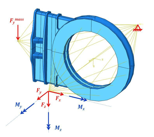
Hello everyone, I have questions about elastoplastic analysis in accordance with ASME VIII div.2. I want to check the valve body for possible types of failures: global failure and local failure in accordance with paragraphs 5.2.4 and 5.3.3 of the regulations.
I read the article PVP2017-65114, where the valve was calculated according to the same criteria.
In this article, the loads on the valve body are given in the form of pressure, external forces and moments without taking into account the flange tension example.
Therefore, there are several questions:
1) To what extent is it appropriate to ignore the precondition from fastener tightening during assembly, such as a spiral wound or RTJ gasket?
2) Factorized loads (with coefficients 2.4 and 1.7) take into account the pre-stress state from fastener tightening or is it still necessary to introduce counter flanges and use contact interaction with the pre-stress state? It is logical to assume that, given the preload, collapse will occur earlier.
3) If, for example, the mating flanges are not modeled, and the loads from the preliminary stress state are applied to the body (tightening force in the first step), in the second step, the reactions of the gaskets and all other loads (pressure, forces and moments from the pipeline).
Do the gasket reactions also need to be multiplied by the factors (2.4 and 1.7)?
4) In the same article, the load causing plastic collapse is obtained using the limit load method, why can't elastoplastic analysis also be used for this? Or ultimate load as a more conservative method in this case?

The task is a test for understanding the rules, thank you.
 
Replies continue below

Recommended for you

I am not experience in Elastic-Plastic Analysis, however I will have a shot at contributing to this discussion.

From Table 5.2:
Table 5.2 (Load Combination Parameters) self-restraining Load said:
The self-restraining load case (i.e., thermal loads, applied displacements). This load case does not typically affect the collapse load, but should be considered in cases where elastic follow-up causes stresses that do not relax sufficiently to redistribute the load without excessive deformation.

I would say that there is no elastic follow-up stresses for bolt pre-loading (educate me if you wish), and therefore applying β to the bolt Pre-load is not required......perhaps.

Have you run an analysis with the bolt displacement increased by β=2.4 with no other operational loads? Did this 'single load analysis' even converge?
 
Hello. DriveMeNuts honestly didn't think of using a betta (2.4) for bolt preload.

There is an open article from 2005 on the calculation of flanges using LIMIT LOAD ANALYSIS OF BOLTED FLANGE CONNECTIONS according to KTA standards. There, the prestress from the bolt load is set in the usual way, and at the second step the load is removed (apparently it is fixed, as, for example, “Lock” in Ansys Worbench) and loads are applied to this already deformed state, first the pressure (the limit is calculated), and then the external load in the same way until convergence. While it is logical to use a linear bolt model for this, this approach seems reasonable for elastoplastic analysis as well.

But since the nonlinear analysis is, in principle, large and complex, then additional nonlinear contacts (friction, surface separation) do not contribute to convergence, and therefore the above questions arose.

That is, if the common practice is to complete the assembly of the valve body with contacts and flanges and most likely a linear bolt model, then you will have to go in this direction, but of course, in terms of the speed of the solution, this is much more costly and difficult.
 
There are two components which need to be assessed. Your question seems to relate to the assessment of the housing.
For the analysis of the flange:
Do the pre-stress step 1 with beta = 1 for pre-stress bolt loads. For step 2, do not fix the flange geometry or remove pre-loads, and apply external housing loads with beta = 2.4. The purpose of this analysis is to assess plastic collapse of the flange and bolts (not the housing). Leaking is also not assessed with this analysis (it will likely leak).
If the flange is simple, FEM could be avoided by assessing plastic collapse and leaking using an industry standard hand calculation, or perhaps the analysis of a similar previous flange design.

For the analysis of the valve housing:
My interpretation of what you describe is that after the pre-load step (identical to the flange analysis above), the bolts should be changed to a rigid body and geometry of the sealing face of the flange is fixed. This makes sense, and I 'think' that additionally, the flange and housing stresses resulting from pre-loading should also remain for subsequent E-P analysis steps.
My recollection of the nature of flange bolt pre-loading, is that during actual operation, the stresses and strains in the bolt and sealing surface do not change, and that only if the flange is over loaded by external loads will the stress in the bolt and flange increase (potentially resulting in a leak). The purpose of this analysis is not to test the strength of the flange or see if it leaks, that was done in the separate analysis/assessment.
Perhaps, you can do away with the pre-stress step and just fix the unstressed flange face and skip to Step 2, because the strains due to pre-stress have little to no effect on the integrity of the housing? Experienced would be able to answer this question.

I'm not sure about Gasket-flange contact interaction during the pre-stress step. For step 2 of the housing analysis, contact interaction doesn't occur because the flange sealing face is fixed.
For step 2 of the housing analysis, you could remove the geometry of the flange because it is essentially fixed, however the displacements and stresses-strains above the flange need to remain.
An E-P analysis can be used. It will be more accurate.
 
Status
Not open for further replies.

Part and Inventory Search

Sponsor